Replacing an Optical Module
Context

Never look directly into an optical
module or the ends of optical fibers. Optical modules and connected
fibers emit laser radiation that will cause eye damage.

Use optical modules certified for Huawei switches. Using other optical modules may affect service stability and Huawei can accept no liability for the outcome.
Ensure that the new optical module has the same center wavelength and complies with the same standards as the old one.
Optical modules are electrostatic-sensitive components. Take ESD protection measures when replacing optical modules.
- Unplug the optical fibers from the optical module before removing it. Install or remove optical fibers carefully to avoid damaging the fiber connectors. Applying too much force to the optical fibers may damage the optical module.
- If an optical module cannot be completely inserted into an optical port, turn the optical module over and try again.
- Cover unconnected optical modules with dust plugs.
Procedure
- Wear an ESD wrist strap or ESD gloves. Ensure that the ESD wrist strap is grounded and in a close contact with your wrist.
- Record the location of each optical fiber on the old optical module and check whether the labels on the optical fibers are correct and clear. If any labels are unclear, replace them and ensure that the details are correct.
- Release the locking clip on the fiber connector, gently
push the fiber connector inward, and then pull out the optical fiber.
After removing the optical fibers from the optical module, cover the
connectors with dust caps.
The locking clip varies on different fiber connectors.
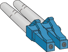
- Figure 1 shows the locking clips on an LC/PC connector. Hold down the locking clips when pulling the optical fibers.
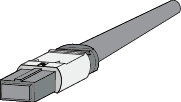
- Figure 2 shows the locking clip on an MPO connector. The locking clip is released automatically when you pull the MPO connector.
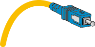
- Figure 3 shows the locking clip on an SC/PC connector. The locking clip is released automatically when you pull the SC/PC connector.
- Remove the optical module and cover the bores with dust
plugs. Store optical module safely.
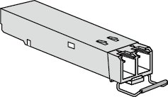
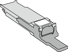
The latch varies on different optical modules. Figure 4 shows an optical module with a clasp latch. To release the clasp latch, rotate it down. Figure 5 shows an optical module with a tab latch. The tab latch is released when you pull it.
- Take out the new optical module from the package. Ensure
that the optical module is correctly oriented and gently push it into
the optical port until you hear a click.

The new optical module must have the same optical parameters as the remote optical module connected to it.
- Identify the optical fibers to be connected to the optical module. Remove the dust caps from the optical fibers and insert the optical fibers to the bores of the optical module.