Example for Configuring Layer 2 Leased Line Access for VPN Users
This section provides an example for configuring L2VPN leased line access for VPN users.
Networking Requirements
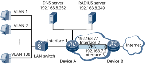
On the network shown in Figure 1, the networking requirements are as follows:
An L2VPN leased line user accesses the Internet through GE 0/1/1.1.
The username of the leased line is l2vpn-leased-line1@isp1, and the password is root@123.
The leased line user belongs to VLAN 10 and obtains an IP address from Device A through DHCP.
RADIUS authentication and RADIUS accounting are used. The IP address of the RADIUS server is 192.168.8.249. The authentication port number is 1812, and the accounting port number is 1813. The RADIUS+1.1 protocol is adopted, and the key is Huawei.
The IP address of the DNS server is 192.168.8.252.
The network-side interface is GE 0/1/2.

Configuration Roadmap
The configuration roadmap is as follows:
Configure authentication and accounting schemes.
Configure a RADIUS server group.
Configure an address pool.
Configure an authentication domain.
Enable basic MPLS functions on the devices.
Set up an LSP between the devices.
Enable MPLS L2VPN on the devices.
Configure a BAS interface.
Data Preparation
To complete the configuration, you need the following data:
Authentication template name and authentication mode
Accounting template name and accounting mode
RADIUS server group name, and IP addresses and port numbers of the RADIUS authentication server and accounting server
IP address pool, gateway address, and DNS server address
Domain name
IP addresses of interfaces
VSI IDs of the two ends of the PW (the IDs must be the same)
MPLS LSR ID of each device
Name of the VSI of each device
VLAN ID and IP address of the sub-interface
BAS interface parameters
Procedure
- Configure an authentication scheme.
<HUAWEI> system-view
[~HUAWEI] sysname DeviceA
[*HUAWEI] commit
[~DeviceA] aaa
[~DeviceA-aaa] authentication-scheme auth1
[*DeviceA-aaa-authen-auth1] authentication-mode radius
[*DeviceA-aaa-authen-auth1] commit
[~DeviceA-aaa-authen-auth1] quit
- Configure an accounting scheme.
[~DeviceA-aaa] accounting-scheme acct1
[*DeviceA-aaa-accounting-acct1] accounting-mode radius
[*DeviceA-aaa-accounting-acct1] commit
[~DeviceA-aaa-accounting-acct1] quit
[~DeviceA-aaa] quit
- Configure a RADIUS server group.
[~DeviceA] radius-server group rd1
[*DeviceA-radius-rd1] radius-server authentication 192.168.8.249 1812
[*DeviceA-radius-rd1] radius-server accounting 192.168.8.249 1813
[*DeviceA-radius-rd1] commit
[~DeviceA-radius-rd1] radius-server type standard
[*DeviceA-radius-rd1] radius-server type plus11
[*DeviceA-radius-rd1] radius-server shared-key Huawei
[*DeviceA-radius-rd1] commit
[~DeviceA-radius-rd1] quit
- Configure an address pool.
[~DeviceA] ip pool pool1 bas local
[*DeviceA-ip-pool-pool1] gateway 11.11.11.1 255.255.0.0
[*DeviceA-ip-pool-pool1] commit
[~DeviceA-ip-pool-pool1] section 0 11.11.11.2 11.11.11.200
[~DeviceA-ip-pool-pool1] dns-server 192.168.8.252
[*DeviceA-ip-pool-pool1] commit
[~DeviceA-ip-pool-pool1] quit
- Configure a domain.
[~DeviceA] aaa
[~DeviceA-aaa] domain isp1
[*DeviceA-aaa-domain-isp1] authentication-scheme auth1
[*DeviceA-aaa-domain-isp1] accounting-scheme acct1
[*DeviceA-aaa-domain-isp1] radius-server group rd1
[*DeviceA-aaa-domain-isp1] commit
[~DeviceA-aaa-domain-isp1] ip-pool pool1
[~DeviceA-aaa-domain-isp1] quit
[~DeviceA-aaa] quit
- Configure GE 1/0/1.1 on Device A.

- L2VPN leased line users cannot go online through main interfaces.
[~DeviceA] interface gigabitethernet 0/1/1.1
[*DeviceA-GigabitEthernet0/1/1.1] commit
[~DeviceA-GigabitEthernet0/1/1.1] vlan-type dot1q 10
[~DeviceA-GigabitEthernet0/1/1.1] quit
- Configure an IGP protocol. In this example, OSPF is used.
# Configure Device A.
[~DeviceA] interface loopback 1
[*DeviceA-LoopBack1] ip address 1.1.1.9 32
[*DeviceA-LoopBack1] commit
[~DeviceA-LoopBack1] quit
[~DeviceA] interface gigabitethernet 0/1/2
[~DeviceA-gigabitethernet0/1/2] ip address 192.168.7.1 24
[*DeviceA-gigabitethernet0/1/2] undo shutdown
[*DeviceA-gigabitethernet0/1/2] quit
[*DeviceA] ospf
[*DeviceA-ospf-1] area 0
[*DeviceA-ospf-1-area-0.0.0.0] network 1.1.1.9 0.0.0.0
[*DeviceA-ospf-1-area-0.0.0.0] network 192.168.7.0 0.0.0.255
[*DeviceA-ospf-1-area-0.0.0.0] quit
[*DeviceA-ospf-1] quit
[*DeviceA] commit
# Configure Device B.
<HUAWEI> system-view
[~HUAWEI] sysname DeviceB
[*HUAWEI] commit
[~DeviceB] interface loopback 1
[*DeviceB-LoopBack1] ip address 2.2.2.9 32
[*DeviceB-LoopBack1] quit
[*DeviceB] interface gigabitethernet 0/1/3
[*DeviceB-gigabitethernet0/1/3] ip address 192.168.7.2 24
[*DeviceB-gigabitethernet0/1/3] undo shutdown
[*DeviceB-gigabitethernet0/1/3] quit
[*DeviceB] ospf
[*DeviceB-ospf-1] area 0
[*DeviceB-ospf-1-area-0.0.0.0] network 2.2.2.9 0.0.0.0
[*DeviceB-ospf-1-area-0.0.0.0] network 192.168.7.0 0.0.0.255
[*DeviceB-ospf-1-area-0.0.0.0] quit
[*DeviceB-ospf-1] quit
[*DeviceB] commit
- Configure basic MPLS functions and LDP.
# Configure Device A.
[~DeviceA] mpls lsr-id 1.1.1.9
[*DeviceA] mpls
[*DeviceA-mpls] lsp-trigger all
[*DeviceA-mpls] quit
[*DeviceA] mpls ldp
[*DeviceA-mpls-ldp] quit
[*DeviceA] interface gigabitethernet 0/1/2
[*DeviceA-gigabitethernet0/1/2] mpls
[*DeviceA-gigabitethernet0/1/2] mpls ldp
[*DeviceA-gigabitethernet0/1/2] quit
[*DeviceA] commit
# Configure Device B.
[~DeviceB] mpls lsr-id 2.2.2.9
[*DeviceB] mpls
[*DeviceB-mpls] lsp-trigger all
[*DeviceB-mpls] quit
[*DeviceB] mpls ldp
[*DeviceB-mpls-ldp] quit
[*DeviceB] interface gigabitethernet 0/1/3
[*DeviceB-gigabitethernet0/1/3] mpls
[*DeviceB-gigabitethernet0/1/3] mpls ldp
[*DeviceB-gigabitethernet0/1/3] quit
[*DeviceB] commit
- Enable MPLS L2VPN, create a VSI, and configure LDP as the signaling protocol.
# Configure Device A.
[~DeviceA] mpls l2vpn
[*DeviceA-l2vpn] quit
[*DeviceA] vsi ldp1 static
[*DeviceA-vsi-ldp1] pwsignal ldp
[*DeviceA-vsi-ldp1-ldp] vsi-id 2
[*DeviceA-vsi-ldp1-ldp] peer 2.2.2.9
[*DeviceA-vsi-ldp1-ldp] commit
[~DeviceA-vsi-ldp1-ldp] quit
[~DeviceA-vsi-ldp1] quit
# Configure Device B.
[~DeviceB] mpls l2vpn
[*DeviceB-l2vpn] quit
[*DeviceB] vsi ldp1 static
[*DeviceB-vsi-ldp1] pwsignal ldp
[*DeviceB-vsi-ldp1-ldp] vsi-id 2
[*DeviceB-vsi-ldp1-ldp] peer 1.1.1.9
[*DeviceB-vsi-ldp1-ldp] quit
[*DeviceB-vsi-ldp1] quit
[*DeviceB] commit
- Configure a BAS interface and bind the VSI to the BAS interface.
# Configure the user-side interface as a BAS interface.
[~DeviceA]interface gigabitethernet0/1/1.1
[~DeviceA-GigabitEthernet0/1/1.1] bas
[~DeviceA-GigabitEthernet0/1/1.1-bas] access-type l2vpn-leased-line user-name l2vpn-leased-line1 password cipher root@123 default-domain authentication isp1
[*DeviceA-GigabitEthernet0/1/1.1-bas] commit
[~DeviceA-GigabitEthernet0/1/1.1-bas] quit
[~DeviceA-GigabitEthernet0/1/1.1] l2 binding vsi ldp1
[*DeviceA-GigabitEthernet0/1/1.1] commit
[~DeviceA-GigabitEthernet0/1/1.1] quit
# Configure the interface on DeviceB.
[~DeviceB] interface gigabitethernet 0/1/1.1
[*DeviceB-GigabitEthernet0/1/1.1] commit
[~DeviceB-GigabitEthernet0/1/1.1] vlan-type dot1q 10
[*DeviceB-GigabitEthernet0/1/1.1] l2 binding vsi ldp1
[*DeviceB-GigabitEthernet0/1/1.1] commit
Configuration Files
#
sysname DeviceA
#
radius-server group rd1
 radius-server shared-key-cipher %^%#`E)v.Q@BHVzxxZ;ij{>&_M0!TGP7YRA@8a7mq<\/%^%#
 radius-server authentication 192.168.8.249 1812 weight 0
 radius-server accounting 192.168.8.249 1813 weight 0
 radius-server type plus11
#
mpls lsr-id 1.1.1.9
#
mpls
 lsp-trigger all
#
mpls l2vpn
#
vsi ldp1 static
 pwsignal ldp
  vsi-id 2
  peer 2.2.2.9
#
mpls ldp
#
ip pool pool1 bas local
 gateway 11.11.11.1 255.255.0.0
 section 0 11.11.11.2 11.11.11.200
 dns-server 192.168.8.252
#
aaa
 #
 authentication-scheme auth1
 #
 accounting-scheme acct1
 #
 domain default0
 #
 domain default1
 #
 domain default_admin
 #
 domain isp1
  authentication-scheme auth1
  accounting-scheme acct1
  radius-server group rd1
  ip-pool pool1
#
interface GigabitEthernet0/1/1
 undo shutdown
#
interface GigabitEthernet0/1/1.1
 vlan-type dot1q 10
 l2 binding vsi ldp1
 bas
 #
  access-type l2vpn-leased-line user-name l2vpn-leased-line1 password cipher %^%#4*RHO=w*}.d\>j09'Z:%=:co~p\w9'G-^|-zR'N4%^%# default-domain authentication isp1
 #
#
interface GigabitEthernet0/1/2
 undo shutdown
 ip address 192.168.7.1 255.255.255.0
 mpls
 mpls ldp
#
interface LoopBack1
 ip address 1.1.1.9 255.255.255.255
#
ospf 1
 area 0.0.0.0
  network 1.1.1.9 0.0.0.0
  network 192.168.7.0 0.0.0.255
#
return
#
sysname DeviceB
#
mpls lsr-id 2.2.2.9
#
mpls
 lsp-trigger all
#
mpls l2vpn
#
vsi ldp1 static
 pwsignal ldp
  vsi-id 2
  peer 1.1.1.9
#
mpls ldp
#
interface GigabitEthernet0/1/1
 undo shutdown
#
interface GigabitEthernet0/1/1.1
 vlan-type dot1q 10
 l2 binding vsi ldp1
#
interface GigabitEthernet0/1/3
 undo shutdown
 ip address 192.168.7.2 255.255.255.0
 mpls
 mpls ldp
#
interface LoopBack1
 ip address 2.2.2.9 255.255.255.255
#
ospf 1
 area 0.0.0.0
  network 2.2.2.9 0.0.0.0
  network 192.168.7.0 0.0.0.255
#
return