Example for Configuring BRAS Access Through L2VPN Termination
This section provides an example for configuring BRAS access through L2VPN termination.
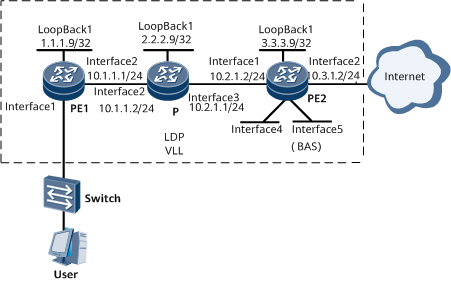
Networking Requirements
On the network shown in Figure 1, PE1, P, and PE2 form a VLL in LDP mode. The router functions as PE2, which is the BRAS. The BRAS user connects to the Internet through the VLL. Two virtual interfaces VE 0/1/32 and VE 0/1/33 are created on the router. VE 0/1/32 terminates the VLL service, and VE 0/1/33.1 functions as a BAS interface to authenticate the user. The requirements are as follows:
The user belongs to the domain isp1 and connects to the Internet through VE 0/1/33.1 as a static user with an IP address of 172.30.0.8, a MAC address of 00e0-fc12-3456
RADIUS authentication and RADIUS accounting are used. The RADIUS server address is 192.168.7.249, and the authentication and accounting port numbers are 1812 and 1813, respectively. RADIUS+1.1 is used, with the key of Huawei.
The accounting and authentication schemes are acct1 and auth1, respectively.

Configuration Roadmap
The configuration roadmap is as follows:
Configure the VE interface for terminating the VLL service and the VE interface for accessing the Internet on the router. Bind the two VE interfaces to a VE-group.
Configure the VLL.
Enable VLL access.
Configure BRAS access on PE2, with VE 0/1/33.1 functioning as a BAS interface.
Data Preparation
To complete the configuration, you need the following data:
VE-group number
L2VPN name
- OSPF parameters
Static user authentication mode, accounting mode, and authentication domain name
- Interface IP addresses
Configuration Procedure
Create two VE interfaces on PE2 and bind them to a VE-group.
# Create VE 0/1/32 for terminating the VLL service.
<HUAWEI> system-view
[~HUAWEI] sysname PE2
[*PE2] commit
[~PE2] interface virtual-ethernet0/1/32
[*PE2-Virtual-Ethernet0/1/32] ve-group 1 l2-terminate
[*PE2-Virtual-Ethernet0/1/32] quit
[*PE2] commit
# Create VE 0/1/33 for accessing the Internet.
[~PE2] interface virtual-ethernet0/1/33
[*PE2-Virtual-Ethernet0/1/33] ve-group 1 l3-access
[*PE2-Virtual-Ethernet0/1/33] quit
[*PE2] commit
Configure the VLL.
# Configure an IGP (for example, OSPF) on the VLL backbone.
When configuring OSPF, advertise the 32-bit IP addresses of the loopback interfaces on the PEs and the P.
For configuration details, see Configuration Files in this section.
# Configure basic MPLS functions and LDP on the MPLS backbone.
Configure PE1.
<HUAWEI> system-view
[~HUAWEI] sysname PE1
[*PE1] commit
[~PE1] mpls lsr-id 1.1.1.9
[*PE1] mpls
[*PE1-mpls] quit
[*PE1] mpls ldp
[*PE1-mpls-ldp] quit
[*PE1] commit
[~PE1] interface gigabitethernet0/1/0
[*PE1-GigabitEthernet0/1/0] mpls
[*PE1-GigabitEthernet0/1/0] mpls ldp
[*PE1-GigabitEthernet0/1/0] undo shutdown
[*PE1-GigabitEthernet0/1/0] quit
[*PE1] commit
Configure the P.
<HUAWEI> system-view
[~HUAWEI] sysname P
[*P] commit
[~P] mpls lsr-id 2.2.2.9
[*P] mpls
[*P-mpls] quit
[*P] commit
[~P] mpls ldp
[*P-mpls-ldp] quit
[*P] commit
[~P] interface gigabitethernet0/1/0
[*P-GigabitEthernet0/1/0] mpls
[*P-GigabitEthernet0/1/0] mpls ldp
[*P-GigabitEthernet0/1/0] undo shutdown
[*P-GigabitEthernet0/1/0] quit
[*P] commit
[~P] interface gigabitethernet0/1/8
[*P-GigabitEthernet0/1/8] mpls
[*P-GigabitEthernet0/1/8] mpls ldp
[*P-GigabitEthernet0/1/8] undo shutdown
[*P-GigabitEthernet0/1/8] quit
[*P] commit
[~P] quit
Configure PE2.
[~PE2] mpls lsr-id 3.3.3.9
[*PE2] mpls
[*PE2-mpls] quit
[*PE2] commit
[~PE2] mpls ldp
[*PE2-mpls-ldp] quit
[*PE2] commit
[~PE2] interface gigabitethernet0/1/32
[*PE2-GigabitEthernet0/1/32] mpls
[*PE2-GigabitEthernet0/1/32] mpls ldp
[*PE2-GigabitEthernet0/1/32] undo shutdown
[*PE2-GigabitEthernet0/1/32] quit
[*PE2] commit
# Set up a remote LDP session between the PEs.
Configure PE1.
[~PE1] mpls ldp remote-peer PE2
[*PE1-mpls-ldp-remote-PE2] remote-ip 3.3.3.9
[*PE1-mpls-ldp-remote-PE2] commit
[~PE1-mpls-ldp-remote-PE2] quit
Configure PE2.
[~PE2] mpls ldp remote-peer PE1
[*PE2-mpls-ldp-remote-PE1] remote-ip 1.1.1.9
[*PE2-mpls-ldp-remote-PE1] commit
[~PE2-mpls-ldp-remote-PE1] quit
# Enable VLL on the PEs and create static VCs.
Create an L2VC on PE1's GE 0/1/32.1.
[~PE1] mpls l2vpn
[*PE1-l2vpn] quit
[*PE1] commit
[~PE1] interface gigabitethernet 0/1/32.1
[*PE1-GigabitEthernet0/1/32.1] vlan-type dot1q 1
[*PE1-GigabitEthernet0/1/32.1] mpls l2vc 3.3.3.9 101
[*PE1-GigabitEthernet0/1/32.1] undo shutdown
[*PE1-GigabitEthernet0/1/32.1] quit
[*PE1] commit
Create an L2VC on PE2's VE 0/1/32.1.
[~PE2] mpls l2vpn
[*PE2-l2vpn] quit
[*PE2] commit
[~PE2] interface virtual-ethernet0/1/32.1
[*PE2-Virtual-Ethernet0/1/32.1] vlan-type dot1q 1
[*PE2-Virtual-Ethernet0/1/32.1] mpls l2vc 1.1.1.9 101
[*PE2-Virtual-Ethernet0/1/32.1] quit
[*PE2] commit
# Verify the configuration.
Check the L2VPN connection information on the PEs. The command output on each PE shows that an L2VC has been set up and its status is up.
The following example uses the command output on PE2.
[~PE2] display mpls l2vc
  Total LDP VC : 1     0 up       1 down
  *client interface     : Virtual-Ethernet0/1/32.1 is up
  Administrator PW       : no
  session state          : down
  AC status              : up
  VC state               : down
  Label state            : 0
  Token state            : 0
  VC ID                  : 101
  VC type                : VLAN
  destination            : 1.1.1.9
  local VC label         : 65665        remote VC label      : 0
  control word           : disable
  remote control word    : none
  forwarding entry       : not exist
  local group ID         : 0
  remote group ID        : 0
  local AC OAM State     : up
  local PSN OAM State    : up
  local forwarding state : not forwarding
  local status code      : 0x1 (not-forwarding)
  BFD for PW             : unavailable
  VCCV State             : up
  manual fault           : not set
  active state           : inactive
  OAM Protocol           : --
  OAM Status             : --
  OAM Fault Type         : --
  PW APS ID              : --
  PW APS Status          : --
  TTL Value              : 1
  link state             : down
  local VC MTU           : 1500         remote VC MTU        : 0
  local VCCV             : alert ttl lsp-ping bfd
  remote VCCV            : none
  tunnel policy name     : --
  PW template name       : --
  primary or secondary   : primary
  load balance type      : flow
  Access-port            : false
  Switchover Flag        : false
  VC tunnel info         : 0 tunnels
  create time            : 0 days, 0 hours, 0 minutes, 17 seconds
  up time                : 0 days, 0 hours, 0 minutes, 0 seconds
  last change time       : 0 days, 0 hours, 0 minutes, 17 seconds
  VC last up time        : 0000/00/00 00:00:00
  VC total up time       : 0 days, 0 hours, 0 minutes, 0 seconds
  CKey                   : 1
  NKey                   : 16782958
  PW redundancy mode     : frr
  AdminPw interface      : --
  AdminPw link state     : --
  Forward state          : send inactive, receive inactive
  Diffserv Mode          : uniform
  Service Class          : --
  Color                  : --
  DomainId               : --
  Domain Name            : --
Configure BRAS access on PE2, with VE 0/1/33.1 functioning as a BAS interface.
# Configuring a Username Generation Mode and Password.
[~PE2] aaa
[~PE2-aaa] default-user-name include sysname
[*PE2-aaa] commit
[~PE2-aaa] default-password cipher Root@123
[*PE2-aaa] commit
# Configure an authentication scheme.
[~PE2-aaa] authentication-scheme auth1
[*PE2-aaa-authen-auth1] authentication-mode radius
[*PE2-aaa-authen-auth1] commit
[~PE2-aaa-authen-auth1] quit
# Configure an accounting scheme.
[~PE2-aaa] accounting-scheme acct1
[*PE2-aaa-accounting-acct1] accounting-mode radius
[*PE2-aaa-accounting-acct1] commit
[~PE2-aaa-accounting-acct1] quit
[~PE2-aaa] quit
# Configure a RADIUS server group.
[~PE2] radius-server group rd1
[*PE2-radius-rd1] radius-server authentication 192.168.7.249 1812
[*PE2-radius-rd1] radius-server accounting 192.168.7.249 1813
[*PE2-radius-rd1] commit
[~PE2-radius-rd1] radius-server type plus11
[*PE2-radius-rd1] radius-server shared-key-cipher Huawei
[*PE2-radius-rd1] commit
[~PE2-radius-rd1] quit
# Configure a local address pool.
[~PE2] ip pool pool1 bas local
[*PE2-ip-pool-pool1] gateway 172.30.1.1 255.255.255.0
[*PE2-ip-pool-pool1] commit
[~PE2-ip-pool-pool1] section 0 172.30.1.2 172.30.1.200
[~PE2-ip-pool-pool1] excluded-ip-address 172.30.1.8
[*PE2-ip-pool-pool1] commit
[~PE2-ip-pool-pool1] quit
# Configure a domain named isp1.
[~PE2] aaa
[~PE2-aaa] domain isp1
[*PE2-aaa-domain-isp1] commit
[~PE2-aaa-domain-isp1] authentication-scheme auth1
[*PE2-aaa-domain-isp1] accounting-scheme acct1
[*PE2-aaa-domain-isp1] radius-server group rd1
[*PE2-aaa-domain-isp1] quit
[*PE2-aaa] quit
[*PE2] commit
# Configure VE 0/1/33.1 as a BAS interface.
[~PE2] interface virtual-ethernet0/1/33.1
[*PE2-Virtual-Ethernet0/1/33.1] commit
[~PE2-Virtual-Ethernet0/1/33.1] user-vlan 1
[~PE2-Virtual-Ethernet0/1/33.1.1-vlan-1-1] quit
[~PE2-Virtual-Ethernet0/1/33.1] bas
[~PE2-Virtual-Ethernet0/1/33.1-bas] access-type layer2-subscriber
[*PE2-Virtual-Ethernet0/5/1.1-bas] authentication-method bind
[*PE2-Virtual-Ethernet0/5/1.1-bas] default-domain authentication isp1
[*PE2-Virtual-Ethernet0/5/1.1-bas] ip-trigger
[*PE2-Virtual-Ethernet0/5/1.1-bas] arp-trigger
[*PE2-Virtual-Ethernet0/5/1.1-bas] commit
[~PE2-Virtual-Ethernet0/5/1.1-bas] quit
[~PE2-Virtual-Ethernet0/5/1.1] quit
Configure a static user.
[~PE2] static-user 172.30.1.8 172.30.1.8 gateway 172.30.1.1 domain-name isp1# Configure GE 0/1/0.
[~PE2] interface GigabitEthernet 0/1/0
[*PE2-GigabitEthernet0/1/0] ip address 10.3.1.2 255.255.255.0
[*PE2-GigabitEthernet0/1/0] commit
Configuration Files
PE1 configuration file
#
sysname PE1
#
mpls lsr-id 1.1.1.9
#
mpls
#
mpls l2vpn
#
mpls ldp
#
mpls ldp remote-peer PE2
 remote-ip 3.3.3.9
#
interface GigabitEthernet0/1/0
 undo shutdown
 ip address 10.1.1.1 255.255.255.0
 mpls
 mpls ldp
#
interface GigabitEthernet0/1/32
 undo shutdown
#
interface GigabitEthernet0/1/32.1
 vlan-type dot1q 1
 mpls l2vc 3.3.3.9 101
#
interface LoopBack1
 ip address 1.1.1.9 255.255.255.255
#
ospf 1
 area 0.0.0.0
  network 1.1.1.9 0.0.0.0
  network 10.1.1.0 0.0.0.255
#
return
P configuration file
#
sysname P
#
mpls lsr-id 2.2.2.9
#
mpls
#
mpls ldp
#
interface GigabitEthernet0/1/0
 undo shutdown
 ip address 10.1.1.2 255.255.255.0
 mpls
 mpls ldp
#
interface GigabitEthernet0/1/8
 undo shutdown
 ip address 10.2.1.1 255.255.255.0
 mpls
 mpls ldp
#
interface LoopBack1
 ip address 2.2.2.9 255.255.255.255
#
ospf 1
 area 0.0.0.0
  network 2.2.2.9 0.0.0.0
  network 10.1.1.0 0.0.0.255
  network 10.2.1.0 0.0.0.255

#
return
PE2 configuration file
#
sysname PE2
#
radius-server group rd1
 radius-server shared-key-cipher %^%#`E)v.Q@BHVzxxZ;ij{>&_M0!TGP7YRA@8a7mq<\/%^%#
 radius-server authentication 192.168.7.249 1645 weight 0
 radius-server accounting 192.168.7.249 1646 weight 0
 radius-server type plus11
#
mpls lsr-id 3.3.3.9
#
mpls
#
mpls l2vpn
#
mpls ldp
#
mpls ldp remote-peer PE1
 remote-ip 1.1.1.9
#
ip pool pool1 bas local
 gateway 172.30.1.1 255.255.255.0
 section 0 172.30.1.2 172.30.1.200
 excluded-ip-address 172.30.1.8
#
aaa
 default-password cipher  %^%#oNUw%i-|"WcBgt8=fSVID7F<=K_N+.(ip[H\:a{D%^%#
 default-user-name include sysname
 #
 authentication-scheme auth1
 #
 accounting-scheme acct1
 #
 domain isp1
  authentication-scheme auth1
  accounting-scheme acct1
  radius-server group rd1
  ip-pool pool1
#
interface GigabitEthernet0/1/0
 ip address 10.3.1.2 255.255.255.0
#
interface GigabitEthernet0/1/32
 ip address 10.2.1.2 255.255.255.0
 mpls
 mpls ldp
#
interface LoopBack1
 ip address 3.3.3.9 255.255.255.255
#
interface Virtual-Ethernet0/1/32
 ve-group 1 l2-terminate
#
interface Virtual-Ethernet0/1/32.1
 vlan-type dot1q 1
 mpls l2vc 1.1.1.9 101
#
interface Virtual-Ethernet0/1/33
 ve-group 1 l3-access
#
interface Virtual-Ethernet0/1/33.1
 user-vlan 1
 bas
 #
  access-type layer2-subscriber
  authentication-method bind
  ip-trigger
  arp-trigger
 #
#
ospf 1
 area 0.0.0.0
  network 3.3.3.9 0.0.0.0
  network 10.2.1.0 0.0.0.255
#
static-user 172.30.1.8 172.30.1.8 gateway 172.30.1.1 domain-name isp1
#
return