Example for Configuring Bit-Error-Triggered Section Switching
This section provides an example for configuring bit-error-triggered section switching.
Networking Requirements
On the network shown in Figure 1, an LDP LSP is deployed between the user provider edge (UPE) and superstratum provider edge (SPE), and LDP auto fast reroute (FRR) is configured. The primary and backup paths of the LDP LSP are UPE <-> SPE and UPE <-> P <-> SPE, respectively. In normal circumstances, traffic between the UPE and SPE travels along the primary path.
If a bit error event occurs on GE0/1/1 of the UPE, traffic traveling along the primary path will be affected. To resolve this problem, configure bit-error-triggered section switching. Then, if GE 0/1/1 on the UPE encounters a bit error event and goes Down, Interior Gateway Protocol (IGP) routes converge, triggering the LDP LSP to switch to the backup path.
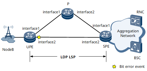

Interfaces 1 through 2 in this example are GE 1/0/0 and GE 1/0/1, respectively.
Configuration Roadmap
The configuration roadmap is as follows:
Configure an IP address and a routing protocol for each interface so that all nodes can communicate at the network layer. This example uses Open Shortest Path First (OSPF) as the routing protocol.
Enable Bidirectional Forwarding Detection (BFD) globally on each node.
Configure an LDP LSP between the UPE and SPE and configure LDP auto FRR.
Enable bit error detection on interfaces along the primary and backup paths of the LDP LSP, configure the switching type of each interface as trigger-section, and set the thresholds for triggering bit error event alarms.
Data Preparation
To complete the configuration, you need the following data:
Interface IP addresses (see Table 1)
Open Shortest Path First (OSPF) process ID (100) and area ID (0.0.0.0)
Multiprotocol Label Switching (MPLS) label switching router (LSR) IDs (Loopback0 interface IP addresses) of each node
Thresholds for triggering bit error event alarms (3*10-4 and 2*10-5)
Configuration Procedure
Configure interface IP addresses.
Configure interface IP addresses according to Table 1 and create a loopback interface on each node. For configuration details, see Configuration Files in this section.
Configure OSPF.
Configure OSPF on each node to allow the nodes to communicate at the network layer. For configuration details, see Configuration Files in this section.
Enable BFD globally.
# Configure the UPE.
<UPE> system-view
[~UPE] bfd
[*UPE-bfd] commit
[~UPE-bfd] quit
Repeat this step for the P and SPE. For configuration details, see Configuration Files in this section.
Enable MPLS and MPLS LDP on each node and the interfaces of each node.
# Configure the UPE.
[~UPE] mpls lsr-id 1.1.1.1
[*UPE] mpls
[*UPE-mpls] mpls ldp
[*UPE-mpls-ldp] quit
[*UPE] interface gigabitethernet 0/1/0
[*UPE-GigabitEthernet0/1/0] mpls
[*UPE-GigabitEthernet0/1/0] mpls ldp
[*UPE-GigabitEthernet0/1/0] quit
[*UPE] interface gigabitethernet 0/1/1
[*UPE-GigabitEthernet0/1/1] mpls
[*UPE-GigabitEthernet0/1/1] mpls ldp
[*UPE-GigabitEthernet0/1/1] quit
[*UPE] commit
# Configure the P.
<P> system-view
[~P] mpls lsr-id 2.2.2.2
[*P] mpls
[*P-mpls] mpls ldp
[*P-mpls-ldp] quit
[*P] interface gigabitethernet 0/1/0
[*P-GigabitEthernet0/1/0] mpls
[*P-GigabitEthernet0/1/0] mpls ldp
[*P-GigabitEthernet0/1/0] quit
[*P] interface gigabitethernet 0/1/1
[*P-GigabitEthernet0/1/1] mpls
[*P-GigabitEthernet0/1/1] mpls ldp
[*P-GigabitEthernet0/1/1] quit
[*P] commit
# Configure the SPE.
<SPE> system-view
[~SPE] mpls lsr-id 4.4.4.4
[*SPE] mpls
[*SPE-mpls] mpls ldp
[*SPE-mpls-ldp] quit
[*SPE] interface gigabitethernet 0/1/0
[*SPE-GigabitEthernet0/1/0] mpls
[*SPE-GigabitEthernet0/1/0] mpls ldp
[*SPE-GigabitEthernet0/1/0] quit
[*SPE] interface gigabitethernet 0/1/1
[*SPE-GigabitEthernet0/1/1] mpls
[*SPE-GigabitEthernet0/1/1] mpls ldp
[*SPE-GigabitEthernet0/1/1] quit
[*SPE] commit
Configure OSPF FRR.
# Configure the UPE.
[~UPE] ospf 100
[~UPE-ospf-100] frr
[*UPE-ospf-100-frr] loop-free-alternate
[*UPE-ospf-100-frr] commit
[~UPE-ospf-100-frr] quit
[~UPE-ospf-100] quit
Configure LDP auto FRR.
# Configure the UPE.
[~UPE] mpls
[~UPE-mpls] mpls ldp
[~UPE-mpls-ldp] auto-frr lsp-trigger all
[*UPE-mpls-ldp] quit
[*UPE] commit
# Run the display mpls lsp command on the UPE to view LDP LSP configurations.
[~UPE] display mpls lsp
-------------------------------------------------------------------------------
                 LSP Information: LDP LSP
-------------------------------------------------------------------------------
FEC                In/Out Label    In/Out IF                      Vrf Name
1.1.1.1/32         4190/NULL       -/-
2.2.2.2/32         NULL/3          -/GE0/1/0
2.2.2.2/32         4191/3          -/GE0/1/0
   **LDP FRR**     NULL/4163       -/GE0/1/1
   **LDP FRR**     4191/4163       -/GE0/1/1
4.4.4.4/32         NULL/4161       -/GE0/1/1
4.4.4.4/32         4192/4161       -/GE0/1/1
   **LDP FRR**     NULL/4163       -/GE0/1/0
   **LDP FRR**     4192/4163       -/GE0/1/0
Enable bit error detection on interfaces along the primary and backup paths of the LDP LSP, configure the switching type of each interface as trigger-section, and set the thresholds for triggering bit error event alarms.
# Configure the UPE.
[~UPE] interface gigabitethernet 0/1/0
[~UPE-GigabitEthernet0/1/0] trap-threshold crc-error packet-error-ratio alarm-threshold 3 4 resume-threshold 2 5 trigger-section
[*UPE-GigabitEthernet0/1/0] quit
[*UPE] interface gigabitethernet 0/1/1
[*UPE-GigabitEthernet0/1/1] trap-threshold crc-error packet-error-ratio alarm-threshold 3 4 resume-threshold 2 5 trigger-section
[*UPE-GigabitEthernet0/1/1] commit
[~UPE-GigabitEthernet0/1/1] quit
# Configure the P.
[~P] interface gigabitethernet 0/1/0
[~P-GigabitEthernet0/1/0] trap-threshold crc-error packet-error-ratio alarm-threshold 3 4 resume-threshold 2 5 trigger-section
[*P-GigabitEthernet0/1/0] quit
[*P] interface gigabitethernet 0/1/1
[*P-GigabitEthernet0/1/1] trap-threshold crc-error packet-error-ratio alarm-threshold 3 4 resume-threshold 2 5 trigger-section
[*P-GigabitEthernet0/1/1] commit
[~P-GigabitEthernet0/1/1] quit
# Configure the SPE.
[~SPE] interface gigabitethernet 0/1/0
[~SPE-GigabitEthernet0/1/0] trap-threshold crc-error packet-error-ratio alarm-threshold 3 4 resume-threshold 2 5 trigger-section
[*SPE-GigabitEthernet0/1/0] quit
[*SPE] interface gigabitethernet 0/1/1
[*SPE-GigabitEthernet0/1/1] trap-threshold crc-error packet-error-ratio alarm-threshold 3 4 resume-threshold 2 5 trigger-section
[*SPE-GigabitEthernet0/1/1] commit
[~SPE-GigabitEthernet0/1/1] quit
Verify the configuration.
In this example, the bit error rate (BER) detected by GE 0/1/1 on the UPE is 9*10-1, exceeding 3*10-4, the threshold for triggering an alarm indicating that a bit error event has occurred. As a result, GE 0/1/1 goes Down. The status change of GE 0/1/1 triggers OSPF route convergence, which in turn triggers the LDP LSP to switch to the backup path.
# Run the display interface GigabitEthernet 0/1/1 command on the UPE. The command output shows that the link protocol status of GE 0/1/1 is DOWN(bit-error-detection down).
[~UPE] display interface GigabitEthernet 0/1/1
GigabitEthernet0/1/1 current state : UP (ifindex: 10)
Line protocol current state : DOWN(bit-error-detection down)
Description:
Route Port,The Maximum Transmit Unit is 1500
Internet Address is 10.1.5.1/24
IP Sending Frames' Format is PKTFMT_ETHNT_2, Hardware address is 00e0-fc12-7890
Loopback:none, LAN full-duplex mode, Pause Flowcontrol: Receive Enable and Send Enable
Last physical up time   : 0000-00-00 00:00:00
Last physical down time : 0000-00-00 00:00:00
Current system time: 2013-01-26 11:42:36
Statistics last cleared:2013-01-16 10:21:54
    Last 300 seconds input rate: 0 bits/sec, 0 packets/sec
    Last 300 seconds output rate: 0 bits/sec, 0 packets/sec
    Input peak rate 0 bits/sec, Record time: -
    Output peak rate 0 bits/sec, Record time: -
    Input: 0 bytes, 13522 packets
    Output: 0 bytes, 13201 packets
    Input:
      Unicast: 1953 packets, Multicast: 11559 packets
      Broadcast: 10 packets, JumboOctets: 0 packets
      CRC: 0 packets, Symbol: 0 packets
      Overrun: 0 packets, InRangeLength: 0 packets
      LongPacket: 0 packets, Jabber: 0 packets, Alignment: 0 packets
      Fragment: 0 packets, Undersized Frame: 0 packets
      RxPause: 0 packets
    Output:
      Unicast: 7009 packets, Multicast: 6184 packets
      Broadcast: 8 packets, JumboOctets: 0 packets
      Lost: 0 packets, Overflow: 0 packets, Underrun: 0 packets
      System: 0 packets, Overruns: 0 packets
      TxPause: 0 packets
    Last 300 seconds input utility rate:  0.00%
    Last 300 seconds output utility rate: 0.00%
# Run the tracert lsp ip 4.4.4.4 32 command on the UPE. The command output shows that the LDP LSP switched to the backup path.
[~UPE] tracert lsp ip 4.4.4.4 32
  LSP Trace Route FEC: IPV4 PREFIX 4.4.4.4/32 , press CTRL_C to break.
TTL    Replier            Time    Type      Downstream
0                                 Ingress   10.1.1.2/[4163 ]
1      10.1.1.2           9       Transit   10.1.3.2/[4161 ]
2      4.4.4.4            8       Egress
Configuration Files
Configuration file of the UPE
#
sysname UPE
#
bfd
#
mpls lsr-id 1.1.1.1
#
mpls
#
mpls ldp
 #
 ipv4-family
  auto-frr lsp-trigger all
#
interface GigabitEthernet0/1/0
 undo shutdown
 ip address 10.1.1.1 255.255.255.0
 mpls
 mpls ldp
 trap-threshold crc-error packet-error-ratio alarm-threshold 3 4 resume-threshold 2 5 trigger-section
#
interface GigabitEthernet0/1/1
 undo shutdown
 ip address 10.1.5.1 255.255.255.0
 mpls
 mpls ldp
 trap-threshold crc-error packet-error-ratio alarm-threshold 3 4 resume-threshold 2 5 trigger-section
#
interface LoopBack0
 ip address 1.1.1.1 255.255.255.255
#
ospf 100
 frr
  loop-free-alternate
 area 0.0.0.0
  network 1.1.1.1 0.0.0.0
  network 10.1.1.0 0.0.0.255
  network 10.1.5.0 0.0.0.255
#
return
Configuration file of the P
#
sysname P
#
bfd
#
mpls lsr-id 2.2.2.2
#
mpls
#
mpls ldp
 #
 ipv4-family
#
interface GigabitEthernet0/1/0
 undo shutdown
 ip address 10.1.1.2 255.255.255.0
 mpls
 mpls ldp
 trap-threshold crc-error packet-error-ratio alarm-threshold 3 4 resume-threshold 2 5 trigger-section
#
interface GigabitEthernet0/1/1
 undo shutdown
 ip address 10.1.3.1 255.255.255.0
 mpls
 mpls ldp
 trap-threshold crc-error packet-error-ratio alarm-threshold 3 4 resume-threshold 2 5 trigger-section
#
interface LoopBack0
 ip address 2.2.2.2 255.255.255.255
#
ospf 100
 area 0.0.0.0
  network 2.2.2.2 0.0.0.0
  network 10.1.1.0 0.0.0.255
  network 10.1.3.0 0.0.0.255
#
return
Configuration file of the SPE
#
sysname SPE
#
bfd
#
mpls lsr-id 4.4.4.4
#
mpls
#
mpls ldp
 #
 ipv4-family
#
interface GigabitEthernet0/1/0
 undo shutdown
 ip address 10.1.3.2 255.255.255.0
 mpls
 mpls ldp
 trap-threshold crc-error packet-error-ratio alarm-threshold 3 4 resume-threshold 2 5 trigger-section
#
interface GigabitEthernet0/1/1
 undo shutdown
 ip address 10.1.5.2 255.255.255.0
 mpls
 mpls ldp
 trap-threshold crc-error packet-error-ratio alarm-threshold 3 4 resume-threshold 2 5 trigger-section
#
interface LoopBack0
 ip address 4.4.4.4 255.255.255.255
#
ospf 100
 area 0.0.0.0
  network 4.4.4.4 0.0.0.0
  network 10.1.3.0 0.0.0.255
  network 10.1.5.0 0.0.0.255
#
return