Example for Associating MAC-Layer SD Alarms with E-PW APS
In E-PW APS scenarios, MPLS-TP OAM is used to monitor the status of a static single-segment (SS) PW. An E-Trunk is configured to determine the master/backup PE status. This section provides an example for associating MAC-layer SD alarms with E-PW APS.
Networking Requirements
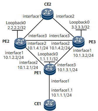
On the public network shown in Figure 1, three PEs belong to the same IGP domain, and static bidirectional co-routed LSPs must be deployed. CE1 and CE2 must reliably communicate through the three PEs on the public network.

Interfaces 1 through 3 in this example represent GigabitEthernet0/1/0, GigabitEthernet0/1/1 and GigabitEthernet0/1/2 respectively.Subinterface1 represents GigabitEthernet0/1/0.1.
Configuration Roadmap
The configuration roadmap is as follows:
Assign an IP address to each interface and configure a routing protocol.
Configure MPLS and public network tunnels.
In this example, a static bidirectional co-routed LSP is established between PE1 and PE2, between PE1 and PE3, and between PE2 and PE3. The required configurations include:
Configure basic MPLS functions and enable MPLS TE.
Configure an MPLS TE tunnel interface.
Configure the ingress and egress for each static bidirectional co-routed LSP.
Bind tunnel interfaces on PE2 and PE3 to static bidirectional co-routed LSPs.
Configure AC dual-homing protection, which requires the following:
- Configure an Eth-Trunk on PE2, PE3, and CE2.
- Configure an E-Trunk on PE2 and PE3 to determine the master/backup status.
Configure PWs in a PW APS/E-PW APS group. This example uses static PWs and requires the following:
Configure a primary PW between PE1 and PE2.
Configure a secondary PW between PE1 and PE3.
Configure a bypass PW between PE2 and PE3.
Configure PW APS/E-PW APS, which requires the following:
Configure a common PW APS instance on PE1.
Configure an E-PW APS instance on PE2 and PE3.
Bind PWs to the PW APS/E-PW APS instances.
Configure MPLS-TP OAM to monitor the PW status, which requires the following:
Create ME instances and bind them to PWs.
Enable CC and CV functions for PWs.
Configure MPLS-TP OAM to monitor the LSP status, which requires the following:
Create an ME instance and bind it to TE tunnels.
Enable CC and CV functions for PWs.
Enable the MAC-layer SD alarm function, configure alarm generation and clearing thresholds, and associate bit error alarms with E-PW APS. These require the following:
- Enable the AIS function globally on PE1, PE2, and PE3.
- Enable the MAC-layer SD alarm function on PE1, PE2, and PE3, configure alarm generation and clearing thresholds, and associate bit error alarms with E-PW APS.
Data Preparation
To complete the configuration, you need the following data:
PEs' interface numbers and IP addresses, and OSPF process numbers
PEs' LSR IDs, tunnel interface numbers and IP addresses, incoming and outgoing tunnel labels, next hop address or outbound interface name on the ingress of each static bidirectional co-routed LSP, and inbound interface name on the egress of each static bidirectional co-routed LSP
L2VC destination IP addresses, VC IDs, VC types, and transmit/receive labels of static PWs
APS instance number on PE1, and roles, local numbers, and remote numbers of the E-PW APS instances on PE2 and PE3
MPLS-TP OAM MEG name, and local and remote MEG IDs
Eth-Trunk number, and E-Trunk LACP system ID and priority
MAC-layer SD alarm generation and clearing thresholds
Procedure
- Assign an IP address to each interface and configure a routing protocol.
Configure an IP address and mask for each interface based on Figure 1. For configuration details, see Configuration Files in this section.
In this example, OSPF is used as an IGP for PE1, PE2, and PE3 to communicate at the network layer. For configuration details, see Configuration Files in this section.
- Configure MPLS and public network tunnels.
In this example, a static bidirectional co-routed LSP is established between PE1 and PE2, between PE1 and PE3, and between PE2 and PE3.
- Configure the ingress and egress for each static bidirectional co-routed LSP.
A static bidirectional co-routed LSP on an ingress can go up only when the LSP name is the same as the tunnel interface name on the ingress. Note that the first letter of the tunnel interface name must be uppercase. This restriction does not apply to transit nodes or the egress.
# Configure PE1 as the ingress for the static bidirectional co-routed LSP from PE1 to PE2 and from PE1 to PE3.
[~PE1] bidirectional static-cr-lsp ingress Tunnel 10
[*PE1-bi-static-ingress-Tunnel10] forward nexthop 10.1.2.2 out-label 20
[*PE1-bi-static-ingress-Tunnel10] backward in-label 30
[*PE1] bidirectional static-cr-lsp ingress Tunnel 20
[*PE1-bi-static-ingress-Tunnel20] forward nexthop 10.1.3.2 out-label 40
[*PE1-bi-static-ingress-Tunnel20] backward in-label 50
[*PE1-bi-static-ingress-Tunnel20] quit
[*PE1] commit
# Configure PE2 as the egress of the static bidirectional co-routed LSP from PE2 to PE1 and as the ingress of the static bidirectional co-routed LSP from PE2 to PE3.
[~PE2] bidirectional static-cr-lsp egress tunnel 10
[*PE2-bi-static-ingress-Tunnel10] forward in-label 20 lsrid 1.1.1.1 tunnel-id 100
[*PE2-bi-static-ingress-Tunnel10] backward nexthop 10.1.2.1 out-label 30
[*PE2] bidirectional static-cr-lsp ingress Tunnel 30
[*PE2-bi-static-ingress-Tunnel30] forward nexthop 10.1.4.2 out-label 60
[*PE2-bi-static-ingress-Tunnel30] backward in-label 70
[*PE2-bi-static-ingress-Tunnel30] quit
[*PE2] commit
# Configure PE3 as the egress for the static bidirectional co-routed LSP from PE1 to PE3 and from PE2 to PE3.
[~PE3] bidirectional static-cr-lsp egress tunnel 20
[*PE3-bi-static-ingress-Tunnel20] forward in-label 40 lsrid 1.1.1.1 tunnel-id 200
[*PE3-bi-static-ingress-Tunnel20] backward nexthop 10.1.3.1 out-label 50
[*PE3-bi-static-ingress-Tunnel20] quit
[*PE3] bidirectional static-cr-lsp egress tunnel 30
[*PE3-bi-static-ingress-Tunnel30] forward in-label 60 lsrid 2.2.2.2 tunnel-id 300
[*PE3-bi-static-ingress-Tunnel30] backward nexthop 10.1.4.1 out-label 70
[*PE3-bi-static-ingress-Tunnel30] quit
[*PE3] commit
- Configure the ingress and egress for each static bidirectional co-routed LSP.
- Configure AC dual-homing protection.
- Configure a PW protection group.
This example uses static PWs.
- Configure static PWs.
When configuring a static PW, you must specify the VC ID. If you do not specify the VC ID, the PW cannot be bound to a PW APS instance.
# Configure the primary and secondary PWs on PE1.
[~PE1] mpls l2vpn
[*PE1-l2vpn] quit
[*PE1] interface gigabitethernet 0/1/0
[*PE1-GigabitEthernet0/1/0] undo shutdown
[*PE1-GigabitEthernet0/1/0] quit
[*PE1] interface gigabitethernet 0/1/0.1
[*PE1-GigabitEthernet0/1/0.1] vlan-type dot1q 10
[*PE1-GigabitEthernet0/1/0.1] mpls static-l2vc destination 2.2.2.2 1 transmit-vpn-label 100 receive-vpn-label 200 tunnel-policy policy1 control-word
[*PE1-GigabitEthernet0/1/0.1] mpls static-l2vc destination 3.3.3.3 2 transmit-vpn-label 300 receive-vpn-label 400 tunnel-policy policy1 control-word secondary
[*PE1-GigabitEthernet0/1/0.1] quit
[*PE1] commit
# Configure the primary and bypass PWs on PE2.
[~PE2] mpls l2vpn
[*PE2-l2vpn] quit
[*PE2] interface eth-trunk 10
[*PE2-Eth-Trunk10] quit
[*PE2] interface eth-trunk 10.1
[*PE2-Eth-Trunk10.1] vlan-type dot1q 10
[*PE2-Eth-Trunk10.1] mpls static-l2vc destination 1.1.1.1 1 transmit-vpn-label 200 receive-vpn-label 100 tunnel-policy policy1 control-word
[*PE2-Eth-Trunk10.1] mpls static-l2vc destination 3.3.3.3 3 transmit-vpn-label 500 receive-vpn-label 600 tunnel-policy policy1 control-word bypass
[*PE2-Eth-Trunk10.1] quit
[*PE2] commit
# Configure the secondary and bypass PWs on PE3.
[~PE3] mpls l2vpn
[*PE3-l2vpn] quit
[*PE3] interface eth-trunk 10
[*PE3-Eth-Trunk10] quit
[*PE3] interface eth-trunk 10.1
[*PE3-Eth-Trunk10.1] vlan-type dot1q 10
[*PE3-Eth-Trunk10.1] mpls static-l2vc destination 1.1.1.1 2 transmit-vpn-label 400 receive-vpn-label 300 tunnel-policy policy1 control-word
[*PE3-Eth-Trunk10.1] mpls static-l2vc destination 2.2.2.2 3 transmit-vpn-label 600 receive-vpn-label 500 tunnel-policy policy1 control-word bypass
[*PE3-Eth-Trunk10.1] quit
[*PE3] commit
- Configure static PWs.
- Configure E-PW APS.
- Configure MPLS-TP OAM to monitor the PW status.
MPLS-TP OAM goes up only when the same MEG name is configured at both ends of a PW.
# Configure PE1.
[~PE1] mpls-tp meg primary
[*PE1-mpls-tp-meg-primary] me l2vc peer-ip 2.2.2.2 vc-id 1 vc-type vlan mep-id 1 remote-mep-id 2
[*PE1-mpls-tp-meg-primary] cc send enable
[*PE1-mpls-tp-meg-primary] cc receive enable
[*PE1-mpls-tp-meg-primary] quit
[*PE1] mpls-tp meg secondary
[*PE1-mpls-tp-meg-secondary] me l2vc peer-ip 3.3.3.3 vc-id 2 vc-type vlan mep-id 3 remote-mep-id 4
[*PE1-mpls-tp-meg-secondary] cc send enable
[*PE1-mpls-tp-meg-secondary] cc receive enable
[*PE1-mpls-tp-meg-secondary] quit
[*PE1] commit
# Configure PE2.
[~PE2] mpls-tp meg primary
[*PE2-mpls-tp-meg-primary] me l2vc peer-ip 1.1.1.1 vc-id 1 vc-type vlan mep-id 2 remote-mep-id 1
[*PE2-mpls-tp-meg-primary] cc send enable
[*PE2-mpls-tp-meg-primary] cc receive enable
[*PE2-mpls-tp-meg-primary] quit
[*PE2] commit
# Configure PE3.
[~PE3] mpls-tp meg secondary
[*PE3-mpls-tp-meg-secondary] me l2vc peer-ip 1.1.1.1 vc-id 2 vc-type vlan mep-id 4 remote-mep-id 3
[*PE3-mpls-tp-meg-secondary] cc send enable
[*PE3-mpls-tp-meg-secondary] cc receive enable
[*PE3-mpls-tp-meg-secondary] quit
[*PE3] commit
Check MPLS-TP OAM configurations on PE1.
[~PE1] display mpls-tp oam meg -------------------------------------------------- MEG primary -------------------------------------------------- MEG Name : primary MEG Level : 7 ME Count : 1 CC Send : enable CC Receive : enable CC Interval : 1000 CC Exp : 7 RDI : enable AIS : disable AIS Interval : 1000 AIS Exp : 7 Lock : disable Lock Interval : 1000 Lock Exp : 7 CSF : disable CSF Interval : 1000 CSF Exp : 7 LM Single-end Receive : disable LM Single-end Proactive : disable LM Single-end SD1 Threshold : 999999 LM Single-end SD2 Threshold : 1000000 LM Ring SD1 Threshold : 0 LM Ring SD2 Threshold : 0 LM Dual-end : disable LM Dual-end SD1 Threshold : 1 LM Dual-end SD2 Threshold : 10 LM Oam-packet SD1 Threshold : 0 LM Oam-packet SD2 Threshold : 0 [ME 1] Index : 0 Direction : dual MEP ID : 1 Remote MEP ID : 2 Status Board : 1 Service Type : vll-pw Peer IP : 2.2.2.2 Remote Peer IP : - VC ID : 1 VC Type : VLAN TTL : 255 State : UP Local State : Near-End Available Far-End Available Alarm Indicate : no alarm Hardware Resouce : - GAL : disable Hardware Error Info : None -------------------------------------------------- -------------------------------------------------- MEG secondary -------------------------------------------------- MEG Name : secondary MEG Level : 7 ME Count : 1 CC Send : enable CC Receive : enable CC Interval : 1000 CC Exp : 7 RDI : enable AIS : disable AIS Interval : 1000 AIS Exp : 7 Lock : disable Lock Interval : 1000 Lock Exp : 7 CSF : disable CSF Interval : 1000 CSF Exp : 7 LM Single-end Receive : disable LM Single-end Proactive : disable LM Single-end SD1 Threshold : 999999 LM Single-end SD2 Threshold : 1000000 LM Ring SD1 Threshold : 0 LM Ring SD2 Threshold : 0 LM Dual-end : disable LM Dual-end SD1 Threshold : 1 LM Dual-end SD2 Threshold : 10 LM Oam-packet SD1 Threshold : 0 LM Oam-packet SD2 Threshold : 0 [ME 1] Index : 1 Direction : dual MEP ID : 3 Remote MEP ID : 4 Status Board : 1 Service Type : vll-pw Peer IP : 3.3.3.3 Remote Peer IP : - VC ID : 1 VC Type : VLAN TTL : 255 State : UP Local State : Near-End Available Far-End Available Alarm Indicate : no alarm Hardware Resouce : - GAL : disable Hardware Error Info : None -------------------------------------------------- -------------------------------------------------- Total MEG number: 2 Total ME number : 2, 0 init, 2 up, 0 down - Configure MPLS-TP OAM to monitor the LSP status.
MPLS-TP OAM goes up only when the same MEG name is configured at both ends of an LSP.
# Configure PE1.
[~PE1] mpls-tp meg 1
[*PE1-mpls-tp-meg-1] me te interface  Tunnel 0/1/0 mep-id 1 remote-mep-id 2
[*PE1-mpls-tp-meg-1] cc send enable
[*PE1-mpls-tp-meg-1] cc receive enable
[*PE1-mpls-tp-meg-1] quit
[*PE1] mpls-tp meg 2
[*PE1-mpls-tp-meg-2] me te interface  Tunnel 0/1/1 mep-id 3 remote-mep-id 4
[*PE1-mpls-tp-meg-2] cc send enable
[*PE1-mpls-tp-meg-2] cc receive enable
[*PE1-mpls-tp-meg-2] quit
[*PE1] commit
# Configure PE2.
[~PE2] mpls-tp meg 1
[*PE2-mpls-tp-meg-1] me te interface  Tunnel 0/1/0 mep-id 2 remote-mep-id 1
[*PE2-mpls-tp-meg-1] cc send enable
[*PE2-mpls-tp-meg-1] cc receive enable
[*PE2-mpls-tp-meg-1] quit
[*PE2] commit
# Configure PE3.
[~PE3] mpls-tp meg 2
[*PE3-mpls-tp-meg-2] me te interface  Tunnel 0/1/1 mep-id 4 remote-mep-id 3
[*PE3-mpls-tp-meg-2] cc send enable
[*PE3-mpls-tp-meg-2y] cc receive enable
[*PE3-mpls-tp-meg-2] quit
[*PE3] commit
Check MPLS-TP OAM configurations on PE1.
[~PE1] display mpls-tp oam meg -------------------------------------------------- MEG 1 -------------------------------------------------- MEG Name : 1 MEG Level : 7 ME Count : 1 CC Send : enable CC Receive : enable CC Interval : 1000 CC Exp : 7 RDI : enable AIS : disable AIS Interval : 1000 AIS Exp : 7 Lock : disable Lock Interval : 1000 Lock Exp : 7 CSF : disable CSF Interval : 1000 CSF Exp : 7 LM Single-end Receive : disable LM Single-end Proactive : disable LM Single-end SD1 Threshold : 999999 LM Single-end SD2 Threshold : 1000000 LM Ring SD1 Threshold : 0 LM Ring SD2 Threshold : 0 LM Dual-end : disable LM Dual-end SD1 Threshold : 1 LM Dual-end SD2 Threshold : 10 LM Oam-packet SD1 Threshold : 0 LM Oam-packet SD2 Threshold : 0 [ME 1] Index : 0 Direction : dual MEP ID : 1 Remote MEP ID : 2 Status Board : 1 Service Type : te (cr-static-lsp) Tunnel-name : tunnel 10 LSP Name : - State : UP Local State : Near-End Available Far-End Available Alarm Indicate : no alarm Hardware Resouce : - GAL : 13 Hardware Error Info : None -------------------------------------------------- -------------------------------------------------- MEG 2 -------------------------------------------------- MEG Name : 2 MEG Level : 7 ME Count : 1 CC Send : enable CC Receive : enable CC Interval : 1000 CC Exp : 7 RDI : enable AIS : disable AIS Interval : 1000 AIS Exp : 7 Lock : disable Lock Interval : 1000 Lock Exp : 7 CSF : disable CSF Interval : 1000 CSF Exp : 7 LM Single-end Receive : disable LM Single-end Proactive : disable LM Single-end SD1 Threshold : 999999 LM Single-end SD2 Threshold : 1000000 LM Ring SD1 Threshold : 0 LM Ring SD2 Threshold : 0 LM Dual-end : disable LM Dual-end SD1 Threshold : 1 LM Dual-end SD2 Threshold : 10 LM Oam-packet SD1 Threshold : 0 LM Oam-packet SD2 Threshold : 0 [ME 1] Index : 0 Direction : dual MEP ID : 3 Remote MEP ID : 4 Status Board : 1 Service Type : te (cr-static-lsp) Tunnel-name : tunnel 20 LSP Name : - State : UP Local State : Near-End Available Far-End Available Alarm Indicate : no alarm Hardware Resouce : - GAL : 13 Hardware Error Info : None -------------------------------------------------- -------------------------------------------------- Total MEG number: 2 Total ME number : 2, 0 init, 2 up, 0 down ============================================================= - Enable the MAC-layer SD alarm function, configure alarm generation and clearing thresholds, and associate bit error alarms with E-PW APS.
- Verify the configuration.
# Run the display port-error-info command. The command output shows that alarm status is Yes.
[~PE1] display port-error-info interface GigabitEthernet0/1/1
GigabitEthernet0/1/1 port-error information
================================================================================
 input-error                            | output-error
--------------------------------------------------------------------------------
 trap enable    : Yes                   | trap enable    : Yes
 trigger down   : No                    | trigger down   : No
 alarm status   : No                    | alarm status   : No
 threshold high : 1000                  | threshold high : 1000
 threshold low  : 100                   | threshold low  : 100
 interval       : 10    sec.            | interval       : 10    sec.
 stat(h)        : 0                     | stat(h)        : 0
 stat(l)        : 0                     | stat(l)        : 0
================================================================================
 crc-error                              | symbol-error
--------------------------------------------------------------------------------
 trap enable    : No                    | trap enable    : Yes
 trigger down   : No                    | trigger down   : No
 alarm status   : No                    | alarm status   : No
 threshold high : 3                     | threshold high : 1000
 threshold low  : 3                     | threshold low  : 100
 percent        : 0                     | N/A            : N/A
 interval       : 10    sec.            | interval       : 10    sec.
 stat(h)        : 0                     | stat(h)        : 0
 stat(l)        : 0                     | stat(l)        : 0
================================================================================
 mac-fcs-sd                             |  mac-fcs-exc
--------------------------------------------------------------------------------
 trap enable     : Yes                  | trap enable       : No
 trigger lsp     : No                   | trigger lsp      : No
 alarm status    : Yes                  | alarm status      : No
 alarm threshold : 1E-5                 | alarm threshold   : 0E-0
 resume threshold: 1E-6                 | resume threshold  : 0E-0
 current value   : 1E-2                 | current value     : 1E-2
 simulation      : Yes                  | simulation        : Yes
# Run the display mpls-tp oam meg command in the view of PE2's GE 0/1/0. The command output shows that Alarm Indicate is CRC-AIS.
[~PE2] interface gigabitethernet0/1/0
[~PE2-GigabitEthernet0/1/0] display mpls-tp oam meg primary
--------------------------------------------------
MEG primary
--------------------------------------------------
MEG Name                      : primary
MEG Level                     : 7
ME Count                      : 1
CC Send                       : enable
CC Receive                    : enable
CC Interval                   : 1000
CC Exp                        : 7
RDI                           : enable
AIS                           : disable
AIS Interval                  : 1000
AIS Exp                       : 7
Lock                          : disable
Lock Interval                 : 1000
Lock Exp                      : 7
CSF                           : disable
CSF Interval                  : 1000
CSF Exp                       : 7
LM Single-end Receive         : disable
LM Single-end Proactive       : disable
LM Single-end SD1 Threshold   : 999999
LM Single-end SD2 Threshold   : 1000000
LM Ring SD1 Threshold         : 0
LM Ring SD2 Threshold         : 0
LM Dual-end                   : disable
LM Dual-end SD1 Threshold     : 1
LM Dual-end SD2 Threshold     : 10
LM Oam-packet SD1 Threshold   : 0
LM Oam-packet SD2 Threshold   : 0
[ME 1]

Index                         : 0
Direction                     : dual
MEP ID                        : 1
Remote MEP ID                 : 2
Status Board                  : 1
Service Type                  : vll-pw
Peer IP                       : 2.2.2.2
Remote Peer IP                : -
VC ID                         : 1
VC Type                       : VLAN
TTL                           : 255
State                         : DOWN
Local State                   : Near-End Available
                                Far-End Available
Alarm Indicate                : CRC-AIS
Hardware Resouce              : -
GAL                           : disable
Hardware Error Info           : None
--------------------------------------------------
--------------------------------------------------

Total MEG number: 1
Total ME number : 1, 0 init, 0 up, 1 down
# Run the display mpls l2vpn pw-aps command in the view of PE1's GE 0/1/2. The command output shows that Request Result is Protect.
[~PE1] interface gigabitethernet0/1/2
[~PE1-GigabitEthernet0/1/2] display mpls l2vpn pw-aps
 Total APSNumber: 1
 Local Id    Remote Id    Status    Request Result    Role    Total VPN Number
 ------------------------------------------------------------------------------
 1           --           SF        Protect              --      2
Configuration Files
CE1 configuration file
#
sysname CE1
#
interface GigabitEthernet0/1/0
 undo shutdown
#
interface GigabitEthernet0/1/0.1
 vlan-type dot1q 10
 ip address 10.1.1.1 255.255.255.0
#
return
PE1 configuration file
#
sysname PE1
#
mpls-tp ais enable
#
mpls lsr-id 1.1.1.1
mpls
 mpls te
#
mpls l2vpn
#
pw-aps 1
#
bidirectional static-cr-lsp ingress tunnel 10
 forward nexthop 10.1.2.2 out-label 20
 backward in-label 30
#
bidirectional static-cr-lsp ingress tunnel 20
 forward nexthop 10.1.3.2 out-label 40
 backward in-label 50
#
interface GigabitEthernet0/1/0.1
 vlan-type dot1q 10
 mpls static-l2vc destination 2.2.2.2 1 transmit-vpn-label 100 receive-vpn-label
 200 tunnel-policy policy1 control-word
 mpls static-l2vc destination 3.3.3.3 2 transmit-vpn-label 300 receive-vpn-label
 400 tunnel-policy policy1 control-word secondary
 mpls l2vpn pw-aps 1 admin
#
interface GigabitEthernet0/1/1
 undo shutdown
 ip address 10.1.2.1 255.255.255.0
 mpls
 mpls te
 trap-threshold crc-error mac-fcs-sd alarm-threshold 3 7 resume-threshold 5 5 trigger-lsp
#
interface GigabitEthernet0/1/2
 undo shutdown
 ip address 10.1.3.1 255.255.255.0
 mpls
 mpls te
#
interface LoopBack0
 ip address 1.1.1.1 255.255.255.255
#
interface tunnel 10
 ip address unnumbered interface LoopBack0
 tunnel-protocol mpls te
 destination 2.2.2.2
 mpls te signal-protocol cr-static
 mpls te tunnel-id 100
 mpls te bidirectional
 mpls te reserved-for-binding
#
interface tunnel 20
 ip address unnumbered interface LoopBack0
 tunnel-protocol mpls te
 destination 3.3.3.3
 mpls te signal-protocol cr-static
 mpls te tunnel-id 200
 mpls te bidirectional
 mpls te reserved-for-binding
#
ospf 1
 area 0.0.0.0
  network 10.1.2.0 0.0.0.255
  network 1.1.1.1 0.0.0.0
  network 10.1.3.0 0.0.0.255
#
tunnel-policy policy1
 tunnel binding destination 2.2.2.2 te tunnel 10
 tunnel binding destination 3.3.3.3 te tunnel 20
#
mpls-tp meg primary
 me l2vc peer-ip 2.2.2.2 vc-id 1 vc-type vlan mep-id 1 remote-mep-id 2
 cc send enable
 cc receive enable
#
mpls-tp meg secondary
 me l2vc peer-ip 3.3.3.3 vc-id 2 vc-type vlan mep-id 3 remote-mep-id 4
 cc send enable
 cc receive enable
#
mpls-tp meg 1
 me te interface  Tunnel 0/1/0 mep-id 1 remote-mep-id 2
 cc send enable
 cc receive enable
#
mpls-tp meg 2
 me te interface  Tunnel 0/1/1 mep-id 3 remote-mep-id 4
 cc send enable
 cc receive enable
#
return
PE2 configuration file
#
sysname PE2
#
mpls-tp ais enable
#
lacp e-trunk system-id 00e0-fc12-7890
lacp e-trunk priority 100
#
mpls lsr-id 2.2.2.2
mpls
 mpls te
#
mpls l2vpn
#
interface GigabitEthernet0/1/2
 undo shutdown
 eth-trunk 10
 trap-threshold crc-error mac-fcs-sd alarm-threshold 3 7 resume-threshold 5 5 trigger-lsp
#
pw-aps 2
 role slave
 remote-aps 3
#
bidirectional static-cr-lsp ingress tunnel 30
 forward nexthop 10.1.4.2 out-label 60
 backward in-label 70
#
bidirectional static-cr-lsp egress tunnel 10
 forward in-label 20 lsrid 1.1.1.1 tunnel-id 100
 backward nexthop 10.1.2.1 out-label 30
#
e-trunk 10
 priority 10
 peer-address 3.3.3.3 source-address 2.2.2.2
#
interface Eth-Trunk10
 mode lacp-static
 e-trunk 10
#
interface Eth-Trunk10.1
 vlan-type dot1q 10
 mpls static-l2vc destination 1.1.1.1 1 transmit-vpn-label 200 receive-vpn-label
 100 tunnel-policy policy1 control-word
 mpls static-l2vc destination 3.3.3.3 3 transmit-vpn-label 500 receive-vpn-label
 600 tunnel-policy policy1 control-word bypass
 mpls l2vpn pw-aps 2 admin
#
interface GigabitEthernet0/1/0
 undo shutdown
 ip address 10.1.2.2 255.255.255.0
 mpls
 mpls te
#
interface GigabitEthernet0/1/1
 undo shutdown
 ip address 10.1.4.1 255.255.255.0
 mpls
 mpls te
#
interface LoopBack0
 ip address 2.2.2.2 255.255.255.255
#
interface tunnel 10
 ip address unnumbered interface LoopBack0
 tunnel-protocol mpls te
 destination 1.1.1.1
 mpls te signal-protocol cr-static
 mpls te tunnel-id 100
 mpls te passive-tunnel
 mpls te binding bidirectional static-cr-lsp egress tunnel 10
 mpls te reserved-for-binding
#
interface tunnel 30
 ip address unnumbered interface LoopBack0
 tunnel-protocol mpls te
 destination 3.3.3.3
 mpls te signal-protocol cr-static
 mpls te tunnel-id 300
 mpls te bidirectional
 mpls te reserved-for-binding
#
ospf 1
 area 0.0.0.0
  network 2.2.2.2 0.0.0.0
  network 10.1.4.0 0.0.0.255
  network 10.1.2.0 0.0.0.255
#
tunnel-policy policy1
 tunnel binding destination 1.1.1.1 te tunnel 10
 tunnel binding destination 3.3.3.3 te tunnel 30
#
mpls-tp meg primary
 me l2vc peer-ip 1.1.1.1 vc-id 1 vc-type vlan mep-id 2 remote-mep-id 1
 cc send enable
 cc receive enable
 me te peer-ip 1.1.1.1 vc-id 1 vc-type vlan mep-id 2 remote-mep-id 1
 cc send enable
 cc receive enable
#
mpls-tp meg 1
 me te interface  Tunnel 0/1/0 mep-id 2 remote-mep-id 1
 cc send enable
 cc receive enable
#
return
PE3 configuration file
#
sysname PE3
#
mpls-tp ais enable
#
lacp e-trunk system-id 00e0-fc12-7890
lacp e-trunk priority 100
#
mpls lsr-id 3.3.3.3
mpls
 mpls te
#
mpls l2vpn
#
interface GigabitEthernet0/1/2
 undo shutdown
 eth-trunk 10
#
pw-aps 3
 role master
 remote-aps 2
#
bidirectional static-cr-lsp egress tunnel 20
 forward in-label 40 lsrid 1.1.1.1 tunnel-id 200
 backward nexthop 10.1.3.1 out-label 50
#
bidirectional static-cr-lsp egress tunnel 30
 forward in-label 60 lsrid 2.2.2.2 tunnel-id 300
 backward nexthop 10.1.4.1 out-label 70
#
#
e-trunk 10
 priority 20
 peer-address 2.2.2.2 source-address 3.3.3.3
#
interface Eth-Trunk10
 mode lacp-static
 e-trunk 10
#
interface Eth-Trunk10.1
 vlan-type dot1q 10
 mpls static-l2vc destination 1.1.1.1 2 transmit-vpn-label 400 receive-vpn-label
 300 tunnel-policy policy1 control-word
 mpls static-l2vc destination 2.2.2.2 3 transmit-vpn-label 600 receive-vpn-label
 500 tunnel-policy policy1 control-word bypass
 mpls l2vpn pw-aps 3 admin
#
interface GigabitEthernet0/1/0
 undo shutdown
 ip address 10.1.3.2 255.255.255.0
 mpls
 mpls te
 trap-threshold crc-error mac-fcs-sd alarm-threshold 3 7 resume-threshold 5 5 trigger-lsp

#
interface GigabitEthernet0/1/1
 undo shutdown
 ip address 10.1.4.2 255.255.255.0
 mpls
 mpls te
#
interface LoopBack0
 ip address 3.3.3.3 255.255.255.255
#
interface tunnel 20
 ip address unnumbered interface LoopBack0
 tunnel-protocol mpls te
 destination 1.1.1.1
 mpls te signal-protocol cr-static
 mpls te tunnel-id 200
 mpls te passive-tunnel
 mpls te binding bidirectional static-cr-lsp egress tunnel 20
 mpls te reserved-for-binding
#
interface tunnel 30
 ip address unnumbered interface LoopBack0
 tunnel-protocol mpls te
 destination 2.2.2.2
 mpls te signal-protocol cr-static
 mpls te tunnel-id 300
 mpls te passive-tunnel
 mpls te binding bidirectional static-cr-lsp egress tunnel 30
 mpls te reserved-for-binding
#
ospf 1
 area 0.0.0.0
  network 3.3.3.3 0.0.0.0
  network 10.1.3.0 0.0.0.255
  network 10.1.4.0 0.0.0.255
#
static-cr-lsp egress 1to2 incoming-interface GigabitEthernet0/1/1 in-label 20
#
tunnel-policy policy1
 tunnel binding destination 1.1.1.1 te tunnel 20
 tunnel binding destination 2.2.2.2 te tunnel 30
#
mpls-tp meg secondary
 me l2vc peer-ip 1.1.1.1 vc-id 2 vc-type vlan mep-id 4 remote-mep-id 3
 cc send enable
 cc receive enable
#
mpls-tp meg 2
 me te interface Tunnel 0/1/1 mep-id 3 remote-mep-id 4
 cc send enable
 cc receive enable
#
return
CE2 configuration file
#
sysname CE2
#
interface GigabitEthernet0/1/1
 undo shutdown
 eth-trunk 10

#
interface Eth-Trunk10
 portswitch
 port trunk allow-pass vlan 10
 mode lacp-static
#
interface GigabitEthernet0/1/0
 undo shutdown
 eth-trunk 10
#
return