Example for Configuring Bit-Error-Triggered Protection Switching on an NG MVPN
This section provides an example for configuring bit-error-triggered protection switching in an NG MVPN scenario.
Networking Requirements
In an NG MVPN scenario, multicast data flows must be transmitted on a link that has no or few bit errors because even low bit error rates may cause black screen, erratic display, or frame interruption. You can configure IS-IS bit error detection and bit-error-triggered protection switching, allowing the mLDP tunnel end to select a new outbound interface if the interface in use is suffering a high bit error rate.
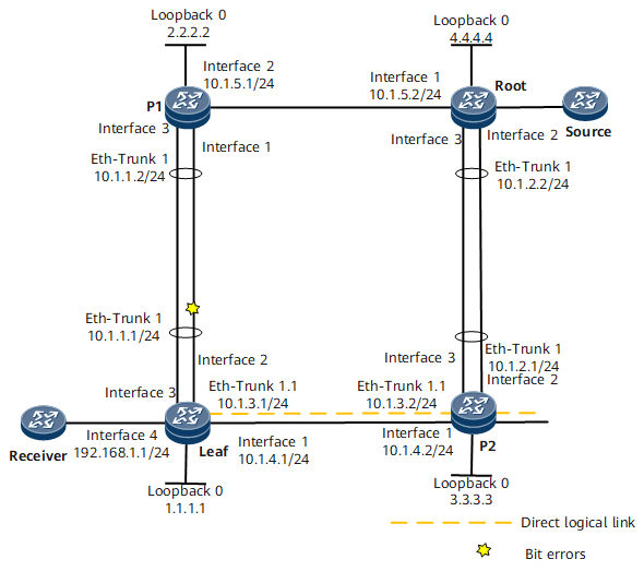
If no bit error occurs on the links, the primary NG MVPN mLDP link is Leaf-P1-Root. If bit errors occur on interface 2 of the leaf node, the link Leaf-P2-Root becomes the primary one. P2 receives the bit error rate information sent by the leaf node, triggering the mLDP tunnel to select interface 1 as the downstream outbound interface. In this example, the advanced IS-IS topology is configured across the entire network, and the primary LSP tunnel of MPLS mLDP is created in the advanced topology.

Interfaces 1 through 4 in this example represent GE 0/1/0, GE 0/1/1, GE 0/1/2, and GE 0/1/3, respectively.
Configuration Roadmap
The configuration roadmap is as follows:
Bind the interfaces connecting P1 and the leaf node to Eth-Trunk 1. Bind the interfaces connecting P2 and the root node to Eth-Trunk 1.
Establish a VLL PW between P1 and the root node.
Configure the interfaces Eth-Trunk 1.1 of the leaf node and P2 as AC interfaces for the access to the root node and P1.
Configure an IP address for each interface and routing protocols, so that all devices can communicate at the network layer. This example uses the advanced topology of IS-IS routes.
Establish an NG MVPN neighbor relationship between the root and leaf nodes. Configure the leaf node as the mLDP leaf node, and the root node as the mLDP root node.
Enable BFD globally, enable IS-IS bit error detection on the logical direct interfaces Eth-Trunk 1.1 of the leaf node and P2. Enable bit-error-triggered IGP route switching on the interfaces Eth-Trunk 1 of the leaf node and P1.
Data Preparation
To complete the configuration, you need the following data:
IP address of each interface as listed in Figure 1
IS-IS instance ID: 1; advanced topology name: advancedtop; network entity names of P1, root node, leaf node, and P2: 10.0000.0000.0001.00, 10.0000.0000.0002.00, 10.0000.0000.0003.00, and 10.0000.0000.0004.00, respectively
VPN instance name: vpna; RD and vpn-target: 100:100
MPLS L2VPN VSI name: VSI1; VSI ID: 1112
BGP instance ID: 100
VLAN ID of Eth-Trunk 1.1: 100
Procedure
- Bind the interfaces connecting P1 and the leaf node to Eth-Trunk 1. Bind the interfaces connecting P2 and the root node to Eth-Trunk 1.
# Bind GE 0/1/1 and GE 0/1/2 of the leaf node to Eth-Trunk 1.
<HUAWEI> system-view
[~HUAWEI] sysname Leaf
[*HUAWEI] commit
[~Leaf] interface Eth-Trunk 1
[*Leaf-Eth-Trunk1] quit
[*Leaf] interface GigabitEthernet0/1/1
[*Leaf-GigabitEthernet0/1/1] eth-trunk 1
[*Leaf-GigabitEthernet0/1/1] quit
[*Leaf] interface GigabitEthernet0/1/2
[*Leaf-GigabitEthernet0/1/2] eth-trunk 1
[*Leaf-GigabitEthernet0/1/2] quit
[*Leaf] commit
# Bind GE 0/1/0 and GE 0/1/2 of P1 to Eth-Trunk 1.
<HUAWEI> system-view
[~HUAWEI] sysname P1
[*HUAWEI] commit
[~P1] interface Eth-Trunk 1
[*P1-Eth-Trunk1] quit
[*P1] interface GigabitEthernet0/1/0
[*P1-GigabitEthernet0/1/0] eth-trunk 1
[*P1-GigabitEthernet0/1/0] quit
[*P1] interface GigabitEthernet0/1/2
[*P1-GigabitEthernet0/1/2] eth-trunk 1
[*P1-GigabitEthernet0/1/2] quit
[*P1] commit
# Bind GE 0/1/1 and GE 0/1/2 of P2 to Eth-Trunk 1.
<HUAWEI> system-view
[~HUAWEI] sysname P2
[*HUAWEI] commit
[~P2] interface Eth-Trunk 1
[*P2-Eth-Trunk1] quit
[*P2] interface GigabitEthernet0/1/1
[*P2-GigabitEthernet0/1/1] eth-trunk 1
[*P2-GigabitEthernet0/1/1] quit
[*P2] interface GigabitEthernet0/1/2
[*P2-GigabitEthernet0/1/2] eth-trunk 1
[*P2-GigabitEthernet0/1/2] quit
[*P2] commit
# Bind GE 0/1/1 and GE 0/1/2 of the root node to Eth-Trunk 1.
<HUAWEI> system-view
[~HUAWEI] sysname Root
[*HUAWEI] commit
[~Root] interface Eth-Trunk 1
[*Root-Eth-Trunk1] quit
[*Root] interface GigabitEthernet0/1/1
[*Root-GigabitEthernet0/1/1] eth-trunk 1
[*Root-GigabitEthernet0/1/1] quit
[*Root] interface GigabitEthernet0/1/2
[*Root-GigabitEthernet0/1/2] eth-trunk 1
[*Root-GigabitEthernet0/1/2] quit
[*Root] commit
- Configure the sub-interfaces Eth-Trunk 1.1 on the leaf node and P2. Configure IP addresses for the interfaces according to Figure 1. For details, see the configuration files.
- Establish a VLL PW between P1 and the root node.
# Configure the VLL on P1.
[~P1] mpls
[*P1-mpls] quit
[*P1] mpls ldp
[*P1-mpls-ldp] quit
[*P1] mpls l2vpn
[*P1-l2vpn] quit
[*P1] vsi vsi1 static
[*P1-vsi-vsi1] pwsignal ldp
[*P1-vsi-vsi1-ldp] vsi-id 1112
[*P1-vsi-vsi1-ldp] peer 4.4.4.4
[*P1-vsi-vsi1-ldp] quit
[*P1-vsi-vsi1] quit
[*P1] commit
# Configure the VLL on the root node.
[~Root] mpls
[*Root-mpls] quit
[*Root] mpls ldp
[*Root-mpls-ldp] quit
[*Root] mpls l2vpn
[*Root-l2vpn] quit
[*Root] vsi vsi1 static
[*Root-vsi-vsi1] pwsignal ldp
[*Root-vsi-vsi1-ldp] vsi-id 1112
[*Root-vsi-vsi1-ldp] peer 2.2.2.2
[*Root-vsi-vsi1-ldp] quit
[*Root-vsi-vsi1] quit
[*Root] commit
- Configure the sub-interfaces Eth-Trunk 1.1 on the leaf node and P2. Configure the sub-interfaces as AC interfaces for the access to P1 and the root node.
# Configure the AC interface on P1.
[~P1] interface Eth-Trunk 1.1
[*P1-Eth-Trunk1.1] vlan-type dot1q 100
[*P1-Eth-Trunk1.1] l2 binding vsi vsi1
[*P1-Eth-Trunk1.1] quit
[*P1] commit
# Configure the AC interface on the root node.
[~Root] interface Eth-Trunk 1.1
[*Root-Eth-Trunk1.1] vlan-type dot1q 100
[*Root-Eth-Trunk1.1] l2 binding vsi vsi1
[*Root-Eth-Trunk1.1] quit
[*Root-Eth-Trunk1.1] commit
- The sub-interfaces of the leaf node and P2 reside on the same network segment. Run the ping 10.1.3.2 command on the leaf node. The ping operation succeeds.
[~Leaf] ping 10.1.3.2 PING 10.1.3.2: 56 data bytes, press CTRL_C to break Reply from 10.1.3.2: bytes=56 Sequence=1 ttl=255 time=45 ms Reply from 10.1.3.2: bytes=56 Sequence=2 ttl=255 time=3 ms Reply from 10.1.3.2: bytes=56 Sequence=3 ttl=255 time=3 ms Reply from 10.1.3.2: bytes=56 Sequence=4 ttl=255 time=2 ms Reply from 10.1.3.2: bytes=56 Sequence=5 ttl=255 time=2 ms --- 10.1.3.2 ping statistics --- 5 packet(s) transmitted 5 packet(s) received 0.00% packet loss round-trip min/avg/max = 2/11/45 ms - Enable IS-IS on the interfaces of P1, P2, root node, and leaf node. Bind the interfaces to the advanced IS-IS topology. On the leaf node, set the cost values of Eth-Trunk 1.1 and GE 0/1/0 to 100 in the advanced IS-IS topology, so that P1 is preferentially selected as the next hop on the route from the leaf node to the root node 4.4.4.4. Enable LDP and mLDP globally on the four devices. Enable LDP on interfaces. For details, see the configuration files. Configure an advanced IS-IS topology across the entire network. Create the primary LSP of MPLS mLDP in the advanced topology.
# Configure the advanced IS-IS topology on the leaf node.
[~Leaf] ip topology advancedtop
[*Leaf] isis 1
[*Leaf-isis-1] cost-style wide
[*Leaf-isis-1] network-entity 10.0000.0000.0003.00
[*Leaf-isis-1] topology advancedtop topology-id 10
[*Leaf-isis-1-topology-advancedtop] quit
[*Leaf-isis-1] quit
[*Leaf] mpls ldp
[*Leaf-ldp] ipv4-family
[*Leaf-ldp-ipv4] mldp p2mp topo advancedtop
[*Leaf-ldp-ipv4] quit
[*Leaf-ldp] quit
[*Leaf] commit
# Configure the advanced IS-IS topology on P1.
[~P1] ip topology advancedtop
[*P1-isis-1] isis 1
[*P1-isis-1] cost-style wide
[*P1-isis-1] network-entity 10.0000.0000.0001.00
[*P1-isis-1] topology advancedtop topology-id 10
[*P1-isis-1-topology-advancedtop] quit
[*P1] quit
[*P1] mpls ldp
[*P1-ldp] ipv4-family
[*P1-ldp-ipv4] mldp p2mp topo advancedtop
[*P1-ldp-ipv4] quit
[*P1-ldp] quit
[*P1] commit
# Configure the advanced IS-IS topology on the root node.
[~Root] ip topology advancedtop
[*Root-isis-1] isis 1
[*Root-isis-1] cost-style wide
[*Root-isis-1] network-entity 10.0000.0000.0002.00
[*Root-isis-1] topology advancedtop topology-id 10
[*Root-isis-1-topology-advancedtop] quit
[*Root] quit
[*Root] mpls ldp
[*Root-ldp] ipv4-family
[*Root-ldp-ipv4] mldp p2mp topo advancedtop
[*Root-ldp-ipv4] quit
[*Root-ldp] quit
[*Root] commit
# Configure the advanced IS-IS topology on P2.
[~P2] ip topology advancedtop
[*P2-isis-1] isis 1
[*P2-isis-1] cost-style wide
[*P2-isis-1] network-entity 10.0000.0000.0004.00
[*P2-isis-1] topology advancedtop topology-id 10
[*P2-isis-1-topology-advancedtop] quit
[*P2] quit
[*P2] mpls ldp
[*P2-ldp] ipv4-family
[*P2-ldp-ipv4] mldp p2mp topo advancedtop
[*P2-ldp-ipv4] quit
[*P2-ldp] quit
[*P2] commit
- Configure NG MPN. For details about VPN configurations, see the configuration files.
# Configure NG MVPN on the root node.
[~Root] bgp 100
[*Root-bgp] peer 1.1.1.1 as-number 100
[*Root-bgp] peer 1.1.1.1 connect-interface LoopBack0
[*Root-bgp] ipv4-family mvpn
[*Root-bgp-af-mvpn] peer 1.1.1.1 enable
[*Root-bgp-af-mvpn] quit
[*Root-bgp] ipv4-family vpnv4
[*Root-bgp-af-vpnv4] peer 1.1.1.1 enable
[*Root-bgp-af-vpnv4] quit
[*Root-bgp] quit
[*Root] commit
# Configure NG MVPN on the leaf node.
[~Leaf] bgp 100
[*Leaf-bgp] peer 4.4.4.4 as-number 100
[*Leaf-bgp] peer 4.4.4.4 connect-interface LoopBack0
[*Leaf-bgp] ipv4-family mvpn
[*Leaf-bgp-af-mvpn] peer 4.4.4.4 enable
[*Leaf-bgp-af-mvpn] quit
[*Leaf-bgp] ipv4-family vpnv4
[*Leaf-bgp-af-vpnv4] peer 4.4.4.4 enable
[*Leaf-bgp-af-vpnv4] quit
[*Leaf-bgp] quit
[*Leaf] commit
- Enable BFD globally on the leaf node, P1, and P2.
# Enable BFD globally on the leaf node.
[~Leaf] bfd
[*Leaf-bfd] quit
[*Leaf] commit
# Enable BFD globally on P1.
[~P1] bfd
[*P1-bfd] quit
[*P1] commit
# Enable BFD globally on P2.
[~P2] bfd
[*P2-bfd] quit
[*P2] commit
- Enable IS-IS bit error detection on the logical direct sub-interfaces Eth-Trunk 1.1 between the leaf node and P2. Enable bit-error-rate-triggered IGP route switching on the interfaces Eth-Trunk 1 between the leaf node and P1.
# Enable bit-error-rate-triggered IGP route switching on Eth-Trunk 1 of the leaf node.
[~Leaf] interface Eth-Trunk1
[~Leaf-Eth-Trunk1] isis topology advancedtop link-quality low incr-cost max-reachable
[*Leaf-Eth-Trunk1] quit
[*Leaf] commit
# Enable IS-IS bit error detection on Eth-Trunk 1.1 of the leaf node.
[~Leaf] interface Eth-Trunk1.1
[~Leaf-Eth-Trunk1.1] isis bfd bit-error enable
[*Leaf-Eth-Trunk1.1] quit
[*Leaf] commit
# Enable bit-error-rate-triggered IGP route switching on Eth-Trunk 1 of P1.
[~P1] interface Eth-Trunk1
[~P1-Eth-Trunk1] isis topology advancedtop link-quality low incr-cost max-reachable
[*P1-Eth-Trunk1] quit
[*P1] commit
# Enable IS-IS bit error detection on Eth-Trunk 1.1 of P2.
[~P2] interface Eth-Trunk1.1
[~P2-Eth-Trunk1.1] isis bfd bit-error enable
[*P2-Eth-Trunk1.1] quit
[*P2] commit
- Verify the configuration.
# After the configuration is complete, run the display mpls mldp lsp p2mp command on the leaf node. The command output shows that the LSP to the root node is Leaf-P1-Root.
[~Leaf] display mpls mldp lsp p2mp
 An asterisk (*) before a Label means the USCB or DSCB is stale
 An asterisk (*) before a Peer means the session is stale
 -------------------------------------------------------------------------------
                        LSP Information: mLDP P2MP-LSP
 -------------------------------------------------------------------------------
 Root IP        : 4.4.4.4              Instance         : --
 Opaque decoded : LSP-ID 32769
 Opaque value   : 01000400008001
 Lsr Type       : Egress
 Trigger Type   : MVPN
 Upstream Count : 1                    Downstream Count : 0
 Upstream:
   In Label  Peer              MBB State
      48144  2.2.2.2           --
 --------------------------------------------------------------------------------
# If bit errors occur on two devices on the network shown in Figure 1, run the display bfd bit-error-detection session all command on the leaf node and P2. The command outputs show the local bit error rate of the leaf node and the remote bit error rate received by P2.
[~Leaf] display bfd bit-error-detection session all
--------------------------------------------------------------------------------
BFD Bit Error Information:
--------------------------------------------------------------------------------
Session Type            : IP Peer
FSM Board Id            : 3
Fault Type              : Local Interface Fault
Min Tx Interval (ms)    : 1000
Max Tx Interval (ms)    : 30000
Actual Tx Interval (ms) : 30000
Detect Multi            : 3
Destination Port        : 3784
TOS-EXP                 : 7
Local BER               : 1e-2
Remote BER              : 0e-0
--------------------------------------------------------------------------------
IP Peer Information:
-----------------------------------------------------------------------------
Interface               : Eth-Trunk1.1
Source IP Address       : 10.1.3.1
Destination IP Address  : 10.1.3.2
--------------------------------------------------------------------------------

     Total Session Number : 1
[~P2] display bfd bit-error-detection session all
--------------------------------------------------------------------------------
BFD Bit Error Information:
--------------------------------------------------------------------------------
Session Type            : IP Peer
FSM Board Id            : -
Fault Type              : Remote Interface Fault
Min Tx Interval (ms)    : 1000
Max Tx Interval (ms)    : 30000
Actual Tx Interval (ms) : 30000
Detect Multi            : 3
Destination Port        : 3784
TOS-EXP                 : 7
Local BER               : 0e-0
Remote BER              : 1e-2
--------------------------------------------------------------------------------
IP Peer Information:
-----------------------------------------------------------------------------
Interface               : Eth-Trunk1.1
Source IP Address       : 10.1.3.2
Destination IP Address  : 10.1.3.1
--------------------------------------------------------------------------------

     Total Session Number : 1
# After bit errors occur on the link of the leaf end, IS-IS is triggered to adjust the cost value. Run the display mpls mldp lsp p2mp command on the leaf node. The command output shows that the MPLS path to the root node is Leaf-P2-Root. P2 learns the bit error rate through IGP association. mLDP excludes Eth-Trunk 1.1 from the outbound interface selection list and selects GE 0/1/0 as the outbound interface. Run the display mpls mldp lsp p2mp command on P2 to check the outbound interface.
[~P2] display mpls mldp lsp  p2mp
 An asterisk (*) before a Label means the USCB or DSCB is stale
 An asterisk (*) before a Peer means the session is stale
 -------------------------------------------------------------------------------
                        LSP Information: mLDP P2MP-LSP
 -------------------------------------------------------------------------------
 Root IP        : 4.4.4.4              Instance         : --
 Opaque decoded : LSP-ID 32769
 Opaque value   : 01000400008001
 Lsr Type       : Egress
 Trigger Type   : MVPN
 Upstream Count : 1                    Downstream Count : 0
 Upstream:
   In Label  Peer              MBB State
      48139  3.3.3.3           --
 -------------------------------------------------------------------------------
[~P2] display mpls mldp lsp  p2mp
 An asterisk (*) before a Label means the USCB or DSCB is stale
 An asterisk (*) before a Peer means the session is stale
 -------------------------------------------------------------------------------
                        LSP Information: mLDP P2MP-LSP
 -------------------------------------------------------------------------------
 Root IP        : 4.4.4.4              Instance         : --
 Opaque decoded : LSP-ID 32769
 Opaque value   : 01000400008001
 Lsr Type       : Transit
 Trigger Type   : --
 Upstream Count : 1                    Downstream Count : 1
 Upstream:
   In Label  Peer              MBB State
      48133  4.4.4.4           --
 Downstream:
  Out Label  Peer              MBB State     Next Hop        Out Interface
      48145  1.1.1.1           --            10.1.4.1        GigabitEthernet0/1/0
 -------------------------------------------------------------------------------
Configuration Files
Leaf node configuration file
#
sysname Leaf
#
multicast mvpn 1.1.1.1
#
ip vpn-instance vpna
 ipv4-family
  route-distinguisher 100:100
  apply-label per-instance
  vpn-target 200:200 export-extcommunity
  vpn-target 200:200 import-extcommunity
  multicast routing-enable
  mvpn
   c-multicast signaling bgp
   rpt-spt mode
#
ip topology advancedtop
#
bfd
#
mpls lsr-id 1.1.1.1
#
mpls
#
mpls ldp
 mldp p2mp
 #
 ipv4-family
  mldp p2mp topo advancedtop
#
mpls ldp remote-peer 3.3.3.3
#
mpls ldp remote-peer 2.2.2.2
#
isis 1
 cost-style wide
 network-entity 10.0000.0000.0003.00
 #
 topology advancedtop topology-id 10
#
interface Eth-Trunk1
 ip address 10.1.1.1 255.255.255.0
 ip topology advancedtop enable
 isis enable 1
 isis topology advancedtop
 isis topology advancedtop link-quality low incr-cost max-reachable
 mpls
 mpls ldp
#
interface Eth-Trunk1.1
 vlan-type dot1q 100
 ip address 10.1.3.1 255.255.255.0
 ip topology advancedtop enable
 isis enable 1
 isis bfd bit-error enable
 isis topology advancedtop
 isis topology advancedtop cost 100
 mpls
 mpls ldp
#
interface GigabitEthernet0/1/0
 undo shutdown
 ip address 10.1.4.1 255.255.255.0
 ip topology advancedtop enable
 isis enable 1
 isis topology advancedtop
 isis topology advancedtop cost 100
 mpls
 mpls ldp
#
interface GigabitEthernet0/1/1
 undo shutdown
 eth-trunk 1
#
interface GigabitEthernet0/1/3
 undo shutdown
 ip binding vpn-instance vpna
 ip address 192.168.1.1 255.255.255.0
 #
interface GigabitEthernet0/1/2
 undo shutdown
 eth-trunk 1
#
interface LoopBack0
 ip address 1.1.1.1 255.255.255.255
 ip topology advancedtop enable
 isis enable 1
 isis topology advancedtop
#
bgp 100
 peer 4.4.4.4 as-number 100
 peer 4.4.4.4 connect-interface LoopBack0
 #
 ipv4-family unicast
  undo synchronization
  peer 4.4.4.4 enable
 #
 ipv4-family mvpn
  policy vpn-target
  peer 4.4.4.4 enable
 #
 ipv4-family vpnv4
  policy vpn-target
  peer 4.4.4.4 enable
 #
 ipv4-family vpn-instance vpna
  import-route direct
#
return
P1 configuration file
#
sysname P1
#
ip topology advancedtop
#
mpls lsr-id 2.2.2.2
#
mpls
#
mpls l2vpn
#
vsi vsi1 static
 pwsignal ldp
  vsi-id 1112
  peer 4.4.4.4
#
mpls ldp
 mldp p2mp
 #
 ipv4-family
  mldp p2mp topo advancedtop
#
mpls ldp remote-peer 4.4.4.4
#
mpls ldp remote-peer 1.1.1.1
#
isis 1
 cost-style wide
 network-entity 10.0000.0000.0001.00
 #
 topology advancedtop topology-id 10
#
interface Eth-Trunk1
 ip address 10.1.1.2 255.255.255.0
 ip topology advancedtop enable
 isis enable 1
 isis bfd enable
 isis bfd bit-error enable
 isis topology advancedtop
 isis link-quality low incr-cost max-reachable
 mpls
 mpls ldp
#
interface Eth-Trunk1.1
 vlan-type dot1q 100
 l2 binding vsi vsi1
#
interface GigabitEthernet0/1/0
 undo shutdown
 eth-trunk 1
#
interface GigabitEthernet0/1/1
 undo shutdown
 ip address 10.1.5.1 255.255.255.0
 ip topology advancedtop enable
 isis enable 1
 isis topology advancedtop
 mpls
 mpls ldp
#
interface GigabitEthernet0/1/2
 undo shutdown
 eth-trunk 1
#
interface LoopBack0
 ip address 2.2.2.2 255.255.255.255
 ip topology advancedtop enable
 isis enable 1
 isis topology advancedtop
#
return
P2 configuration file
#
sysname P2
#
ip topology advancedtop
#
bfd
#
mpls lsr-id 3.3.3.3
#
mpls
#
mpls ldp
 mldp p2mp
 #
 ipv4-family
  mldp p2mp topo advancedtop
#
mpls ldp remote-peer 4.4.4.4
#
mpls ldp remote-peer 1.1.1.1
#
isis 1
 cost-style wide
 network-entity 10.0000.0000.0004.00
 #
 topology advancedtop topology-id 10
#
interface Eth-Trunk1
 ip address 10.1.2.1 255.255.255.0
 ip topology advancedtop enable
 isis enable 1
 isis topology advancedtop
 mpls
 mpls ldp
#
interface Eth-Trunk1.1
 vlan-type dot1q 100
 ip address 10.1.3.2 255.255.255.0
 ip topology advancedtop enable
 isis enable 1
 isis bfd bit-error enable
 isis topology advancedtop
 mpls
 mpls ldp
#
interface Ethernet3/0/0
 undo shutdown
#
interface GigabitEthernet0/1/0
 undo shutdown
 ip address 10.1.4.2 255.255.255.0
 ip topology advancedtop enable
 isis enable 1
 isis topology advancedtop
 mpls
 mpls ldp
 #
interface GigabitEthernet0/1/1
 undo shutdown
 eth-trunk 1
#
interface GigabitEthernet0/1/2
 undo shutdown
 eth-trunk 1
#
interface LoopBack0
 ip address 3.3.3.3 255.255.255.255
 ip topology advancedtop enable
 isis enable 1
 isis topology advancedtop
#
return
Root node configuration file
#
sysname Root
#
multicast mvpn 4.4.4.4
#
ip vpn-instance vpna
 ipv4-family
  route-distinguisher 100:100
  apply-label per-instance
  vpn-target 100:100 export-extcommunity
  vpn-target 200:200 export-extcommunity
  vpn-target 100:100 import-extcommunity
  vpn-target 200:200 import-extcommunity
  multicast routing-enable
  mvpn
   sender-enable
   c-multicast signaling bgp
   rpt-spt mode
   ipmsi-tunnel
    mldp
#
ip topology advancedtop
#
mpls lsr-id 4.4.4.4
#
mpls
#
mpls l2vpn
#
vsi vsi2 static
 pwsignal ldp
  vsi-id 1112
  peer 2.2.2.2
#
mpls ldp
 mldp p2mp
 #
 ipv4-family
  mldp p2mp topo advancedtop
#
mpls ldp remote-peer 2.2.2.2
#
mpls ldp remote-peer 3.3.3.3
#
isis 1
 cost-style wide
 network-entity 10.0000.0000.0002.00
 #
 topology advancedtop topology-id 10
#
interface Eth-Trunk1
 ip address 10.1.2.2 255.255.255.0
 ip topology advancedtop enable
 isis enable 1
 isis topology advancedtop
 mpls
 mpls ldp
#
interface Eth-Trunk1.1
 vlan-type dot1q 100
 l2 binding vsi vsi2
#
interface GigabitEthernet0/1/0
 undo shutdown
 ip address 10.1.5.2 255.255.255.0
 ip topology advancedtop enable
 isis enable 1
 isis topology advancedtop
 mpls
 mpls ldp
#
interface GigabitEthernet0/1/1
 undo shutdown
 eth-trunk 1
#
interface GigabitEthernet0/1/2
 undo shutdown
 eth-trunk 1
#
interface LoopBack0
 ip address 4.4.4.4 255.255.255.255
 ip topology advancedtop enable
 isis enable 1
 isis topology advancedtop
#
bgp 100
 peer 1.1.1.1 as-number 100
 peer 1.1.1.1 connect-interface LoopBack0
 #
 ipv4-family unicast
  undo synchronization
  peer 1.1.1.1 enable
 #
 ipv4-family mvpn
  policy vpn-target
  peer 1.1.1.1 enable
 #
 ipv4-family vpnv4
  policy vpn-target
  peer 1.1.1.1 enable
#
return