FlexE Shim
The core functions of FlexE are implemented through the FlexE shim. The following uses a FlexE group that consists of 100GE PHYs as an example.
FlexE Shim Mechanism
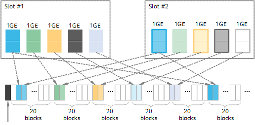
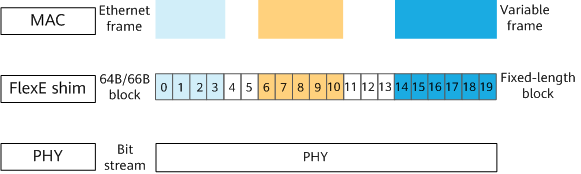
As shown in Figure 1, the FlexE shim divides each 100GE PHY in a FlexE group into 20 timeslots for data transmission, with each timeslot providing bandwidth of 5 Gbit/s. A FlexE client can be flexibly assigned bandwidth that is an integer multiple of 5 Gbit/s. The Ethernet frames of FlexE clients are partitioned into 64B/66B blocks, which are then mapped and distributed to timeslots of a FlexE group according to the calendar mechanism of the FlexE shim, thereby implementing strict isolation between the blocks.
Calendar Mechanism
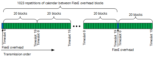
Figure 2 shows the calendar mechanism of the FlexE shim. Twenty blocks (corresponding to timeslots 0 to 19) are used as a logical unit, and 1023 "twenty blocks" are then used as a calendar component. The calendar components are distributed in a specified order into timeslots, each of which has a bandwidth granularity of 5 Gbit/s for data transmission.

In terms of bit streams, each 64B/66B block is carried over a timeslot (basic logical unit carrying the 64B/66B block), as shown in Figure 2.
FlexE allocates available timeslots in a FlexE group based on bandwidth required by each FlexE client to form a mapping from the FlexE client to one or more timeslots. In addition, the calendar mechanism is used to carry one or more FlexE clients in the FlexE group.
Overhead Frame and Multiframe
To transmit configuration and management information between two interconnected FlexE clients, implement link auto-negotiation, and establish client-timeslot mappings, the FlexE shim defines overhead frames to provide in-band management channels. An overhead frame consists of blue overhead blocks shown in Figure 2. Eight overhead blocks form an overhead frame, and 32 overhead blocks form an overhead multiframe. An overhead block is also a 64B/66B block and appears every 1023 "twenty blocks." Fields contained in each overhead block are different.
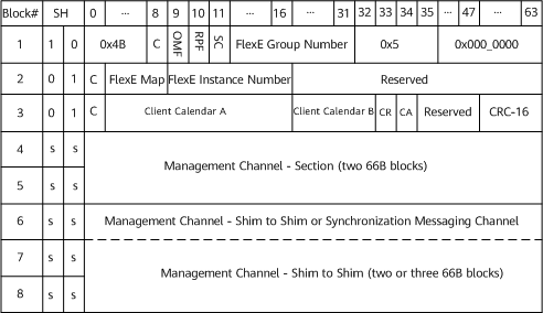
Figure 3 shows the format of an overhead frame, which consists of eight overhead blocks. The first three overhead blocks carry the mappings between timeslots and FlexE clients and between timeslots and FlexE groups, and the remaining ones carry management messages, such as DCN and 1588v2 messages.
The SH is a synchronization header field added after 64B/66B encoding is performed on the data, and its bit width is 2 bits. If the value is 10, the carried data is a control block; if the value is 01, the carried data is a data block; if the value is 00 or 11, the field is invalid; and if the value is ss, the synchronization header is valid and may be 10 or 01.
In an overhead frame, the first overhead block is a control block, the second and third overhead blocks are data blocks, and the fourth to eighth overhead blocks are allocated to management or synchronization messaging channels. Table 1 describes the meaning of each field in an overhead frame.
Field |
Bit Width (Bits) |
Meaning |
|---|---|---|
0x4B |
8 |
Indicates the control field, which is used to lock data synchronization in the receive direction. |
C |
1 |
Indicates the calendar configuration in use. The value 0 indicates that calendar A is used, and the value 1 indicates that calendar B is used. Two calendars are configured to establish timeslot tables A and B for hitless bandwidth adjustment. |
OMF |
1 |
Indicates the overhead multiframe. This field is set to 0 for the first 16 overhead frames of an overhead multiframe or 1 for the last 16 overhead frames. |
RPF |
1 |
Indicates the remote PHY fault. |
SC |
1 |
Indicates the synchronization configuration. The value 0 indicates that the shim-to-shim management channel occupies the sixth to eighth overhead blocks of the overhead frame; the value 1 indicates that the shim-to-shim management channel occupies the seventh and eighth overhead blocks of the overhead frame (the sixth overhead block is allocated to the synchronization messaging channel). |
FlexE Group Number |
20 |
Indicates the group ID defined by the protocol, which must be planned in advance. |
0x5 |
4 |
Indicates the "O" code, which is used to lock data synchronization in the receive direction. |
0x000_0000 |
28 |
Reserved and displayed as all 0s. |
FlexE Map |
8 x 32 |
Indicates the mapping between PHYs and a FlexE group, in bit map format. If a bit is 1, the corresponding PHY belongs to the FlexE group; if a bit is 0, the corresponding PHY does not belong to the FlexE group. A FlexE group formed by 100GE PHYs is used as an example. Because 32 overhead frames form an overhead multiframe, the bit width is 256 (8 x 32) bits, where bits 0 and 255 are reserved and the markable range is 1 to 254. When a PHY ID is 3, only the third bit is 1 and the other bits are all 0 among the 256 bits. |
FlexE Instance Number |
8 |
Indicates a PHY ID, identifying the PHY to which timeslots belong. The PHY IDs must be unique in the same group but can be the same in different groups. |
Reserved |
N/A |
Indicates the reserved field, which is used for possible extension of the protocol in the future. |
Client Calendar |
16 x 20 |
Indicates the correspondence between a client and timeslot. The Client Calendar A and Client Calendar B fields are used to respectively establish timeslot tables A and B for hitless bandwidth adjustment. A FlexE group formed by 100GE PHYs is used as an example. This group has 20 timeslots, and the client IDs occupy the Client Calendar fields of the first 20 overhead frames. |
CR |
1 |
Indicates a calendar switch request. |
CA |
1 |
Indicates a calendar switch acknowledge. |
CRC-16 |
16 |
Indicates the CRC field of the overhead frame. It is mainly used to prevent the timeslot configuration from being damaged in the case of bit errors. The overhead frame is protected by CRC, which is calculated based on the first three overhead blocks. Except the CRC-16 field, other fields with content are used for the calculation, whereas the reserved bits are not. |
Management Channel - Section |
64 |
A section management channel is used to transmit management messages, such as DCN and LLDP messages, between adjacent FlexE nodes. |
Management Channel - Shim to Shim |
64 |
A shim-to-shim management channel is used to transmit management messages, such as DCN and LLDP messages, between E2E FlexE nodes. |
Synchronization Messaging Channel |
64 |
A synchronization messaging channel is used to transmit clock messages, such as 1588v2 messages, between adjacent FlexE nodes. |
Synchronous framing involves the SH, 0x4B, 0x5, and OMF fields in the data receive direction, and is used to identify the first overhead block of the overhead frame. If the SH, 0x4B, and 0x5 fields do not match the expected positions for five times, the FlexE overhead multiframe is unlocked, indicating that the received 32 overhead frames are not from the same overhead multiframe. As a result, the restored timeslot information is incorrect. In addition, if the OMF field passes the CRC, the overhead multiframe is locked when the bit changes from 0 to 1 or from 1 to 0. If an error occurs in a frame, the overhead multiframe is unlocked.
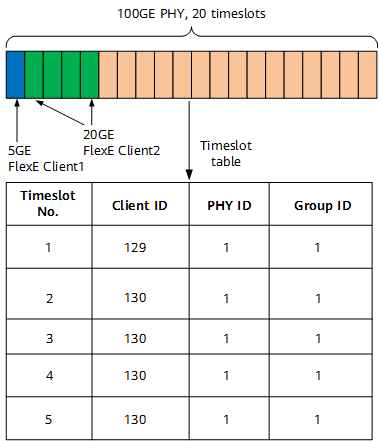
Timeslot Table Establishment
As shown in Figure 4, a FlexE group consisting of 100GE PHYs has twenty 5 Gbit/s timeslots. FlexE Client1 and FlexE Client2 are configured with 5 Gbit/s bandwidth and 20 Gbit/s bandwidth, respectively. The blue timeslot in the figure is allocated to FlexE Client1, and the green timeslots in the figure are allocated to FlexE Client2. In addition, timeslot tables are established using the FlexE Group Number, FlexE Map, FlexE Instance Number, Client Calendar A, and Client Calendar B fields that are carried in the overhead frame. The transmit or receive end then sends or receives packets based on the mappings in the timeslot tables.
According to the timeslot tables, the client IDs, PHY IDs, and group IDs of the interfaces on the two interconnected devices must be consistent.
Hitless Bandwidth Adjustment Through Timeslot Table Switching
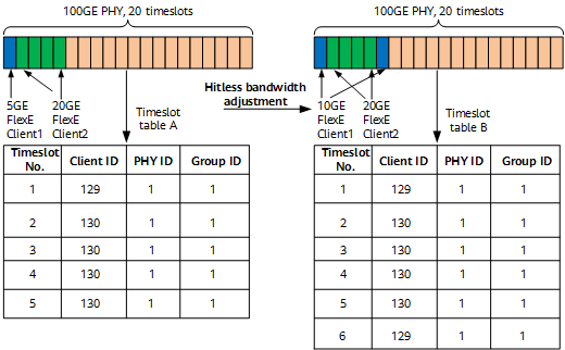
Each FlexE client has two timeslot tables. Only one timeslot table takes effect at any time. When the bandwidth of a FlexE client is adjusted, the timeslot tables need to be switched.
As shown in Figure 5, the bandwidth of FlexE Client1 is adjusted from 5 Gbit/s to 10 Gbit/s. In normal cases, timeslot table A is used for packet sending and receiving, and timeslot table B is used as a backup. During bandwidth adjustment, timeslot table B is used for packet sending and receiving, implementing hitless bandwidth adjustment.
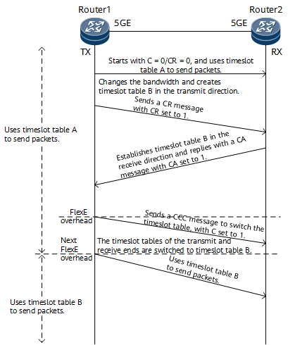
As shown in Figure 6, the timeslot table switching process is as follows:
- FlexE Client1 on Router1 uses timeslot table A to send packets based on 5 Gbit/s bandwidth.
- After the bandwidth of FlexE Client1 is adjusted to 10 Gbit/s, Router1 establishes timeslot table B in the transmit direction and sends a CR message to Router2.
- After receiving the CR message from Router1, Router2 establishes timeslot table B in the receive direction and sends a CA message to Router1, indicating that timeslot table B in the receive direction has been established.
- After receiving the CA message from Router2, Router1 sends a CCC message for timeslot table switching to Router2. After this and in the next timeslot period, both Router1 and Router2 use timeslot table A for packet sending and receiving.
- Router1 uses timeslot table B to send packets after the next timeslot period after Router1 sends the CCC message. After receiving an overhead frame that identifies the next timeslot period, Router2 uses timeslot table B to receive packets.
Similarly, after the bandwidth of FlexE Client1 is adjusted to 10 Gbit/s on Router2, the timeslot table is also changed to timeslot table B in the receive direction of Router1. In this case, both ends use timeslot table B to send and receive packets.
1 Gbit/s Timeslot Granularity Mechanism
The FlexE standards define a default timeslot granularity of 5 Gbit/s. However, Huawei devices support 1 Gbit/s timeslot granularity to better support applications, such as smart grid and mobile edge computing (MEC), in 5G vertical industries. Figure 7 shows how 1 Gbit/s timeslots are provided: if the time of a 5 Gbit/s timeslot is expanded, five 1 Gbit/s data blocks can occupy one standard FlexE 5 Gbit/s timeslot using TDM (blocks of five colors are transmitted in turn to implement five 1 Gbit/s sub-timeslots). In this way, small-granularity sub-timeslots are provided, without breaking the main architecture defined in the FlexE standards.
The 1 Gbit/s timeslot granularity is a sub-timeslot of a 5 Gbit/s timeslot and takes effect only in the 5 Gbit/s timeslot. If the bandwidth exceeds 5 Gbit/s, the 5 Gbit/s timeslot granularity is used.