FlexE Mode Switching
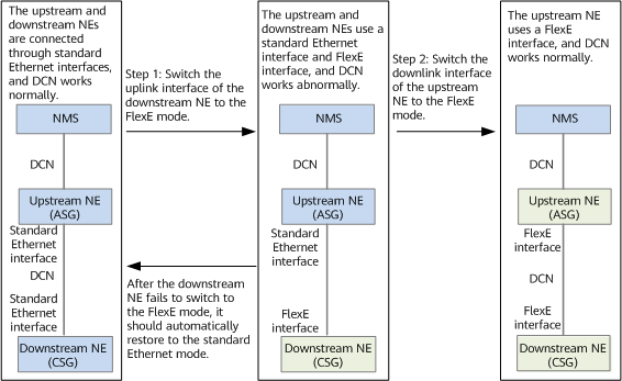
As shown in Figure 1, the upstream and downstream NEs on the live network are connected through standard Ethernet interfaces, and the DCN function works normally. The NMS can manage these NEs. You need to perform the following steps to switch the standard Ethernet interfaces to FlexE-based physical interfaces:
- Switch the uplink interface of the downstream NE to the FlexE mode.
- Switch the downlink interface of the upstream NE to the FlexE mode.
After the interfaces are switched to the FlexE mode, the link connection is automatically added to the topology of the NMS. In addition, the DCN function is enabled by default to allow the NMS to manage the devices.
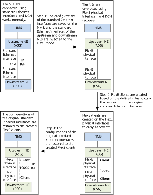
After a standard Ethernet interface is switched to the FlexE mode, the original standard Ethernet interface disappears. A FlexE client needs to be determined based on the defined rules to carry the bandwidth and configuration of the original standard Ethernet interface, implementing configuration restoration. As shown in Figure 2, the configuration restoration process is as follows:
- The configurations of the standard Ethernet interfaces are saved on the NMS, and the standard Ethernet interfaces of the upstream and downstream NEs are switched to the FlexE mode.
- FlexE clients are created based on the defined rules to carry the bandwidth of the original standard Ethernet interfaces.
- The configurations of the original standard Ethernet interfaces are restored to the created FlexE clients.
The bandwidth of a FlexE client can be configured in either of the following modes:
- Set the bandwidth of a FlexE client to the bandwidth of an original standard Ethernet interface. For example, set the bandwidth of a FlexE client to 100 Gbit/s for a 100GE interface. This mode applies to existing network reconstruction scenarios. Before creating a slice, switch the standard Ethernet interface to a FlexE client with the same bandwidth. After the reconstruction is complete, adjust the bandwidth of the FlexE client according to the slice bandwidth requirement and create new slicing interfaces.
- Configure the default slice's bandwidth as the bandwidth of a FlexE client, and reserve other bandwidth for new slices. For example, set the bandwidth of a FlexE client to 50 Gbit/s as the default slice's bandwidth for a 100GE interface, and reserve the remaining 50 Gbit/s bandwidth for new slices.