Networking Modes of Clock Physical Layer Synchronization
Transmitting Clock Signals Through Clock Interfaces
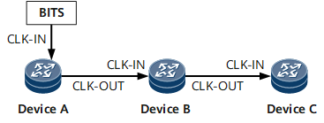
A clock interface on a clock board outputs its clock signals to other network elements.
The NetEngine 8000 F provides two or three building integrated timing supply (BITS) interfaces. One BITS interface is used to input and output clock information. The other BITS interface is used to input and output time information. The third BITS interface can be used for input and output clock information and time information.
As shown in Figure 1, Device A traces the BITS clock. The clock output interface on Device A is connected to the clock input interface on Device B using a clock cable. Devices B and C are also connected using a clock cable, and Device C traces Device B's clock. The clocks of the three Devices synchronize with the BITS clock.
Transmitting Clock Signals Through Physical Links
Transmitting clock signals through physical links is a commonly used method for synchronizing clocks. The information about the master clock is stored in physical link signals. Other network elements extract the clock information from the physical link signals through the clock board and trace and lock the clock information.
Ethernet links can be used to implement clock synchronization without the need of constructing a special clock synchronization network.
The NetEngine 8000 F can transmit or receive clock signals through an Ethernet interface.
As shown in Figure 2, Device A traces the BITS clock. Devices A and B are connected through an Ethernet link. Devices B and C are also connected through an Ethernet link, and Device C traces Device B's clock. The clocks of the three Devices synchronize with the BITS clock.
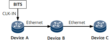
Owing to the long transmission distance of optical fibers, synchronizing clock signals through synchronous Ethernet links has become the most common networking mode for clock synchronization.