Physical Layer Synchronization Modes and Precautions
There are two synchronization modes for digital networks: pseudo synchronization and master/slave synchronization.
Pseudo Synchronization
In pseudo synchronization mode, each switching site has its own clock with very high accuracy and stability, and clock synchronization is not carried out among the switching sites. There is a small difference in the clock frequency or phase among the clocks of the switching sites, which does not affect service transmission and can therefore be ignored. This is the reason why the mode is called pseudo synchronization.
Pseudo synchronization applies to digital networks between countries. Caesium clocks are usually used on digital networks inside a country.
Master/Slave Synchronization
In master/slave synchronization mode, a master clock of high accuracy is set on a network and traced by every site. Every network element traces the higher-level clock in the same site or sub-site. Every sub-site traces the higher-level clock in its own site.
Master/Slave synchronization is classified into two types: direct master/slave synchronization and hierarchical master/slave synchronization.
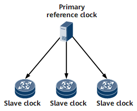
In direct master/slave synchronization mode shown in Figure 1, all slave clocks synchronize with the master clock. Direct master/slave synchronization applies to simple networks.
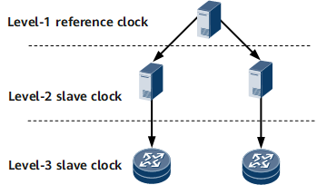
In hierarchical master/slave synchronization mode shown in Figure 2, the devices are classified into three levels. The level-2 slave clock synchronizes with the level-1 reference clock, and the level-3 slave clock synchronizes with the Level-2 slave clock. Hierarchical master/slave synchronization applies to large complex networks.
Master/Slave synchronization generally applies to digital networks inside a country or region where there is one master clock of high accuracy on the network.
To improve the reliability of master/slave synchronization, two master clocks are set on the network. One functions as the active master clock, and the other functions as the standby master clock. Both are caesium clocks. In normal cases, each network element traces the active master clock as does the standby. When the active master clock becomes faulty, the standby automatically becomes the reference clock for the entire network. After the faulty active master clock recovers, it becomes the reference clock again.
A clock board has the following working status in the master/slave synchronization mode:
Trace state
The slave clock traces the clock source provided by a higher level clock. The clock source may be provided either by the master clock or by the internal clock source of the higher-level network element.
Hold-in state
When all reference clocks are lost, the slave clock enters the hold-in state and uses the last frequency stored before the reference clocks were lost. In addition, the slave clock provides clock signals that conform to the source reference clock to ensure that there is a small difference between the frequency of the provided clock signals and that of the reference clock.
Free running state
After losing all external reference clocks, the slave clock loses the clock reference memory or retains the hold-in state for a long time. As a result, the oscillator inside the slave clock works in the free running state.