Example for Configuring BGP Load Balancing
Configuring load balancing can fully utilize network resources and reduce network congestion.
Networking Requirements
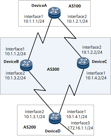
In Figure 1, all routers run BGP; Device A resides in AS 100; Device B and Device C reside in AS 300; Device D resides in AS 200. EBGP connections are established between Device A and Device B, between Device A and Device C, between Device D and Device B, and between Device D and Device C. On Device A, there are two BGP routes to 172.16.1.0/24. Traffic to 172.16.1.0/24 can reach the destination through Device B and Device C. It is required that BGP load balancing be configured to fully utilize network resources and reduce network congestion.

Precautions
You can implement load balancing by setting BGP attributes. For example, you can ignore the comparison of IGP metrics. Perform these configurations only when you can ensure that no routing loops will occur.
Configuration Roadmap
The configuration roadmap is as follows:
Establish EBGP connections between Device A and Device B, and between Device A and Device C, and establish an IBGP connection between Device B and Device C.
Establish EBGP connections between Device D and Device B, and between Device D and Device C.
Configure load balancing on Device A and then check routes.
Data Preparation
To complete the configuration, you need the following data:
Router IDs and AS numbers of Device A, Device B, Device C, and Device D
Number of routes for load balancing
Procedure
- Configure an IP address for each interface. For configuration details, see Configuration Files in this section.
- Configure BGP connections.
# Configure Device A.
[~DeviceA] bgp 100
[*DeviceA-bgp] router-id 1.1.1.1
[*DeviceA-bgp] peer 10.1.1.2 as-number 300
[*DeviceA-bgp] peer 10.1.2.2 as-number 300
[*DeviceA-bgp] commit
[~DeviceA-bgp] quit
# Configure Device B.
[~DeviceB] bgp 300
[*DeviceB-bgp] router-id 2.2.2.2
[*DeviceB-bgp] peer 10.1.1.1 as-number 100
[*DeviceB-bgp] peer 10.1.3.1 as-number 200
[*DeviceB-bgp] commit
[~DeviceB-bgp] quit
# Configure Device C.
[~DeviceC] bgp 300
[*DeviceC-bgp] router-id 3.3.3.3
[*DeviceC-bgp] peer 10.1.2.1 as-number 100
[*DeviceC-bgp] peer 10.1.4.1 as-number 200
[*DeviceC-bgp] commit
[~DeviceC-bgp] quit
# Configure Device D.
[~DeviceD] bgp 200
[*DeviceD-bgp] router-id 4.4.4.4
[*DeviceD-bgp] peer 10.1.3.2 as-number 300
[*DeviceD-bgp] peer 10.1.4.2 as-number 300
[*DeviceD-bgp] ipv4-family unicast
[*DeviceD-bgp-af-ipv4] network 172.16.1.0 255.255.255.0
[*DeviceD-bgp-af-ipv4] commit
[~DeviceD-bgp-af-ipv4] quit
[~DeviceD-bgp] quit
# Check the routing table of Device A.
[~DeviceA] display bgp routing-table 172.16.1.0 24

 BGP local router ID : 1.1.1.1
 Local AS number : 100
 Paths : 2 available, 1 best, 1 select
 BGP routing table entry information of 172.16.1.0/24:
 From: 10.1.1.2 (2.2.2.2)
 Route Duration: 0d00h00m50s
 Direct Out-interface: GigabitEthernet0/1/0
 Original nexthop: 10.1.1.2
 Qos information : 0x0
 AS-path 200 300, origin igp, pref-val 0, valid, external, best, select, pre 255
 Advertised to such 2 peers:
    10.1.1.2
    10.1.2.2

 BGP routing table entry information of 172.16.1.0/24:
 From: 10.1.2.2 (3.3.3.3)
 Route Duration: 0d00h00m51s
 Direct Out-interface: GigabitEthernet0/1/8
 Original nexthop: 10.1.2.2
 Qos information : 0x0
 AS-path 200 300, origin igp, pref-val 0, valid, external, pre 255, not preferred for router ID
 Not advertised to any peers yet
The command output shows that there are two valid routes from Device A to 172.16.1.0/24. The route with the next hop 10.1.1.2 is the optimal route because the router ID of Device B is smaller.
- Configure load balancing.
# Configure load balancing on Device A.
[~DeviceA] bgp 100
[*DeviceA-bgp] ipv4-family unicast
[*DeviceA-bgp-af-ipv4] maximum load-balancing 2
[*DeviceA-bgp-af-ipv4] commit
[~DeviceA-bgp-af-ipv4] quit
[~DeviceA-bgp] quit
- Verify the configuration.
# Check the routing table of Device A.
[~DeviceA] display bgp routing-table 172.16.1.0 24

 BGP local router ID : 1.1.1.1
 Local AS number : 100
 Paths : 2 available, 1 best, 2 select
 BGP routing table entry information of 172.16.1.0/24:
 From: 10.1.1.2 (2.2.2.2)
 Route Duration: 0d00h03m55s
 Direct Out-interface: GigabitEthernet0/1/0
 Original nexthop: 10.1.1.2
 Qos information : 0x0
 AS-path 200 300, origin igp, pref-val 0, valid, external, best, select, pre 255
 Advertised to such 2 peers
    10.1.1.2
    10.1.2.2

 BGP routing table entry information of 172.16.1.0/24:
 From: 10.1.2.2 (3.3.3.3)
 Route Duration: 0d00h03m56s
 Direct Out-interface: GigabitEthernet0/1/8
 Original nexthop: 10.1.2.2
 Qos information : 0x0
 AS-path 200 300, origin igp, pref-val 0, valid, external, select, pre 255, not preferred for router ID
 Not advertised to any peers yet
The command output shows that the BGP route to 172.16.1.0/24 has two next hops, 10.1.1.2 and 10.1.2.2, both of which are preferred.
Configuration Files
Device A configuration file
#
sysname DeviceA
#
interface GigabitEthernet0/1/0
 undo shutdown
 ip address 10.1.1.1 255.255.255.0
#
interface GigabitEthernet0/1/8
 undo shutdown
 ip address 10.1.2.1 255.255.255.0
#
bgp 100
 router-id 1.1.1.1
 peer 10.1.1.2 as-number 300
 peer 10.1.2.2 as-number 300
 #
 ipv4-family unicast
  maximum load-balancing 2
  peer 10.1.1.2 enable
  peer 10.1.2.2 enable
#
return
Device B configuration file
#
sysname DeviceB
#
interface GigabitEthernet0/1/0
 undo shutdown
 ip address 10.1.1.2 255.255.255.0
#
interface GigabitEthernet0/1/8
 undo shutdown
 ip address 10.1.3.2 255.255.255.0
#
bgp 300
 router-id 2.2.2.2
 peer 10.1.1.1 as-number 100
 peer 10.1.3.1 as-number 200
 #
 ipv4-family unicast
  undo synchronization
  peer 10.1.1.1 enable
  peer 10.1.3.1 enable
#
return
Device C configuration file
#
sysname DeviceC
#
interface GigabitEthernet0/1/0
 undo shutdown
 ip address 10.1.4.2 255.255.255.0
#
interface GigabitEthernet0/1/8
 undo shutdown
 ip address 10.1.2.2 255.255.255.0
#
bgp 300
 router-id 3.3.3.3
 peer 10.1.2.1 as-number 100
 peer 10.1.4.1 as-number 200
 #
 ipv4-family unicast
  undo synchronization
  peer 10.1.2.1 enable
  peer 10.1.4.1 enable
#
return
Device D configuration file
#
sysname DeviceD
#
interface GigabitEthernet0/1/0
 undo shutdown
 ip address 10.1.4.1 255.255.255.0
#
interface GigabitEthernet0/1/8
 undo shutdown
 ip address 10.1.3.1 255.255.255.0
#
interface GigabitEthernet0/1/16
 undo shutdown
 ip address 172.16.1.1 255.255.255.0
#
bgp 200
 router-id 4.4.4.4
 peer 10.1.3.2 as-number 300
 peer 10.1.4.2 as-number 300
 #
 ipv4-family unicast
  undo synchronization
  network 172.16.1.0 255.255.255.0
  peer 10.1.3.2 enable
  peer 10.1.4.2 enable
#
return