Example for Configuring Dual-ended Frame Loss Measurement in VPLS Networking
This section provides an example showing how to configure dual-ended frame loss measurement in VPLS networking.
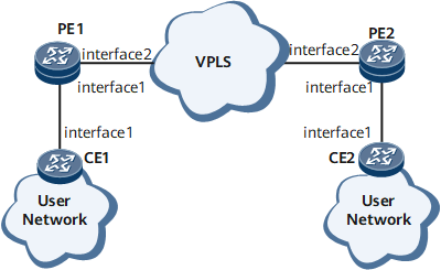
Networking Requirements
As shown in Figure 1, CEs and PEs on end-to-end links support CC. Dual-ended frame loss measurement needs to be implemented to monitor the performance of end-to-end IP RAN links and measure frame loss on the links.

Configuration Roadmap
Configure dual-ended frame loss measurement for the PW between the PEs to continually collect frame loss statistics.
Configure dual-ended frame loss measurement for the AC between each PE and its attached CE to collect frame loss statistics.
Data Preparation
To complete the configuration, you need the following data:
Configure the name of a VSI and the IP address of the interface of a VPLS.
Configure the names of the MD and MA between PE1 and PE2 and between CE1 and PE1.
Configure a VLAN ID on CE interfaces for collecting AC-side packet statistics.
Configure the interval at which LM messages are sent.
Procedure
- Configure dual-ended frame loss measurement for the PW between the PEs.
Configure a VPLS connection.
Configure a VPLS connection between PE1 and PE2. The detailed configurations are not provided here. For details, see the chapter "VPLS Configuration" in the HUAWEI NetEngine 8000 F SeriesRouter Configuration Guide - VPN or configuration files in this example.
After completing the configuration, run the display vsi name vsi-name verbose command on each PE to view information about the related VSI and PW.
<PE1> display vsi  name ldp1 verbose
 ***VSI Name               : ldp1
    Administrator VSI      : no
    Isolate Spoken         : disable
    VSI Index              : 1
    PW Signaling           : ldp
    Member Discovery Style : static
    Bridge-domain Mode     : disable
    PW MAC Learn Style     : unqualify
    Encapsulation Type     : vlan
    MTU                    : 1500
    Diffserv Mode          : uniform
    Service Class          : --
    Color                  : --
    DomainId               : 255
    Domain Name            :
    Ignore AcState         : disable
    P2P VSI                : disable
    Create Time            : 0 days, 0 hours, 10 minutes, 10 seconds
    VSI State              : up

    VSI ID                 : 1
   *Peer Router ID         : 1.1.1.1
    primary or secondary   : primary
    ignore-standby-state   : no
    VC Label               : 4187
    Peer Type              : dynamic
    Session                : up
    Tunnel ID              : 0x0000000001004c4b42
    Broadcast Tunnel ID    : --
    Broad BackupTunnel ID  : --
    CKey                   : 1
    NKey                   : 2281701546
    Stp Enable             : 0
    PwIndex                : 1
    Control Word           : enable

    Interface Name         : GigabitEthernet0/1/1.1
    State                  : up
    Access Port            : false
    Last Up Time           : 2013/02/21 08:44:46
    Total Up Time          : 0 days, 0 hours, 0 minutes, 14 seconds

  **PW Information:

   *Peer Ip Address        : 1.1.1.1
    PW State               : up
    Local VC Label         : 4187
    Remote VC Label        : 4187
    Remote Control Word    : enable
    PW Type                : label
    Tunnel ID              : 0x0000000001004c4b42
    Broadcast Tunnel ID    : --
    Broad BackupTunnel ID  : --
    Ckey                   : 1
    Nkey                   : 2281701546
    Main PW Token          : 0x0
    Slave PW Token         : 0x0
    Tnl Type               : ldp
    OutInterface           : LDP LSP
    Backup OutInterface    : --
    Stp Enable             : 0
    PW Last Up Time        : 2013/02/21 08:44:46
    PW Total Up Time       : 0 days, 0 hours, 0 minutes, 14 seconds
Configure basic Ethernet CFM functions and specify the MEP type as inward.
Configure basic Ethernet CFM functions on each PE. Specify the Ethernet CFM protocol in the version of IEEE Standard 802.1ag-2007. Create an MD named md1 and an MA named ma1, and bind the MA to the VSI.
# Configure PE1.
[~PE1] cfm enable
[*PE1] cfm md md1
[*PE1-md-md1] ma ma1
[*PE1-md-md1-ma-ma1] map vsi ldp1
[*PE1-md-md1-ma-ma1] mep mep-id 1 interface gigabitethernet0/1/1.1 inward
[*PE1-md-md1-ma-ma1] mep ccm-send mep-id 1 enable
[*PE1-md-md1-ma-ma1] remote-mep mep-id 2
[*PE1-md-md1-ma-ma1] remote-mep ccm-receive mep-id 2 enable
[*PE1-md-md1-ma-ma1] test-id 1 mep 1 remote-mep 2 peer-ip 1.1.1.1
[*PE1-md-md1-ma-ma1] commit
# Configure PE2.
[~PE2] cfm enable
[*PE2] cfm md md1
[*PE2-md-md1] ma ma1
[*PE2-md-md1-ma-ma1] map vsi ldp1
[*PE2-md-md1-ma-ma1] mep mep-id 2 interface gigabitethernet0/1/1.1 inward
[*PE2-md-md1-ma-ma1] mep ccm-send mep-id 2 enable
[*PE2-md-md1-ma-ma1] remote-mep mep-id 1
[*PE2-md-md1-ma-ma1] remote-mep ccm-receive mep-id 1 enable
[*PE2-md-md1-ma-ma1] test-id 1 mep 2 remote-mep 1 peer-ip 2.2.2.2
[*PE2-md-md1-ma-ma1] commit
Enable proactive dual-ended frame loss measurement on the PW on the VPLS network.
# Configure PE1.
[~PE1-md-md1-ma-ma1] loss-measure dual-ended continual test-id 1
[*PE1-md-md1-ma-ma1] quit
[*PE1-md-md1] quit
[*PE1-md-md1-ma-ma1] commit
# Configure PE2.
[~PE2-md-md1-ma-ma1] loss-measure dual-ended continual test-id 1
[*PE2-md-md1-ma-ma1] quit
[*PE2-md-md1] quit
[*PE2-md-md1-ma-ma1] commit
Verify the configuration.
Run the display y1731 statistic-type command on PE1 to view dual-ended frame loss statistics.
<PE1> display y1731 statistic-type dual-loss
Latest dual-ended loss statistics of test-id 1:
--------------------------------------------------------------------------------
Index    Local-loss    Local-loss ratio    Remote-loss    Remote-loss ratio
--------------------------------------------------------------------------------
    1             0             0.0000%              0              0.0000%
    2             0             0.0000%              0              0.0000%
    3             0             0.0000%              0              0.0000%
    4             0             0.0000%              0              0.0000%
    5             0             0.0000%              0              0.0000%
    6             0             0.0000%              0              0.0000%
    7             0             0.0000%              0              0.0000%
    8             0             0.0000%              0              0.0000%
--------------------------------------------------------------------------------
Average Local-loss  :          0    Average Local-loss Ratio  :   0.0000%
Maximum Local-loss  :          0    Maximum Local-loss Ratio  :   0.0000%
Minimum Local-loss  :          0    Minimum Local-loss Ratio  :   0.0000%
Average Remote-loss :          0    Average Remote-loss Ratio :   0.0000%
Maximum Remote-loss :          0    Maximum Remote-loss Ratio :   0.0000%
Minimum Remote-loss :          0    Minimum Remote-loss Ratio :   0.0000%
- Configure dual-ended frame loss measurement for the AC between CE1 and PE1.
Configure basic Ethernet CFM functions and specify the MEP type as outward.
Configure basic Ethernet CFM functions on each PE. Specify the Ethernet CFM protocol in the version of IEEE Standard 802.1ag-2007. Create an MD named md1 and an MA named ma2, and bind the MA to the VSI.
# Configure CE1.
<HUAWEI> system-view
[~HUAWEI] sysname CE1
[*HUAWEI] commit
[~CE1] interface gigabitethernet0/1/1
[~CE1-GigabitEthernet0/1/1]portswitch
[*CE1-GigabitEthernet0/1/1]port default vlan 2
[*CE1-GigabitEthernet0/1/1]quit
[*CE1] cfm enable
[*CE1] cfm md md1
[*CE1-md-md1] ma ma2
[*CE1-md-md1-ma-ma2] map vlan 2
[*CE1-md-md1-ma-ma2] mep mep-id 3 interface gigabitethernet0/1/1 outward
[*CE1-md-md1-ma-ma1] mep ccm-send mep-id 3 enable
[*CE1-md-md1-ma-ma1] remote-mep mep-id 4
[*CE1-md-md1-ma-ma1] remote-mep ccm-receive mep-id 4 enable
[*CE1-md-md1-ma-ma1] test-id 2 mep 3 remote-mep 4
[*CE1-md-md1-ma-ma1] commit
# Configure PE1.
[~PE1] cfm md md1
[*PE1-md-md1] ma ma2
[*PE1-md-md1-ma-ma2] map vsi ldp1
[*PE1-md-md1-ma-ma2] mep mep-id 4 interface gigabitethernet0/1/1.1 outward
[*PE1-md-md1-ma-ma2] mep ccm-send mep-id 4 enable
[*PE1-md-md1-ma-ma2] remote-mep mep-id 3
[*PE1-md-md1-ma-ma2] remote-mep ccm-receive mep-id 3 enable
[*PE1-md-md1-ma-ma1] test-id 2 mep 4 remote-mep 3
[*PE1-md-md1-ma-ma1] commit
Enable the proactive dual-ended loss measurement.
# Configure PE1.
[~PE1-md-md1-ma-ma2] loss-measure dual-ended continual test-id 2
[*PE1-md-md1-ma-ma2] quit
[*PE1-md-md1] quit
[*PE1] commit
# Configure CE1.
[~CE1-md-md1-ma-ma2] loss-measure dual-ended continual test-id 2
[*CE1-md-md1-ma-ma2] quit
[*CE1-md-md1] quit
[*CE1] commit
Verify the configuration.
Run the display y1731 statistic-type command on PE1 to view dual-ended frame loss statistics.
<PE1> display y1731 statistic-type dual-loss
Latest dual-ended loss statistics of test-id 1:
--------------------------------------------------------------------------------
Index    Local-loss    Local-loss ratio    Remote-loss    Remote-loss ratio
--------------------------------------------------------------------------------
    1             0             0.0000%              0              0.0000%
    2             0             0.0000%              0              0.0000%
    3             0             0.0000%              0              0.0000%
    4             0             0.0000%              0              0.0000%
    5             0             0.0000%              0              0.0000%
    6             0             0.0000%              0              0.0000%
    7             0             0.0000%              0              0.0000%
    8             0             0.0000%              0              0.0000%
--------------------------------------------------------------------------------
Average Local-loss  :          0    Average Local-loss Ratio  :   0.0000%
Maximum Local-loss  :          0    Maximum Local-loss Ratio  :   0.0000%
Minimum Local-loss  :          0    Minimum Local-loss Ratio  :   0.0000%
Average Remote-loss :          0    Average Remote-loss Ratio :   0.0000%
Maximum Remote-loss :          0    Maximum Remote-loss Ratio :   0.0000%
Minimum Remote-loss :          0    Minimum Remote-loss Ratio :   0.0000%
Configuration Files
CE1 configuration file
#
 sysname CE1
#
 vlan batch 2
#
 cfm version standard
 cfm enable
#
interface GigabitEthernet0/1/1
 undo shutdown
 port default vlan 2
#
 cfm md md1
  ma ma2
   map vlan 2
   mep mep-id 3 interface GigabitEthernet0/1/1 outward
   mep ccm-send mep-id 3 enable
   remote-mep mep-id 4
   remote-mep ccm-receive mep-id 4 enable
   test-id 2 mep 3 remote-mep 4
   loss-measure dual-ended continual test-id 2
#
return
PE1 configuration file
#
 sysname PE1
#
 cfm version standard
 cfm enable
#
 mpls lsr-id 2.2.2.2
 mpls
#
 mpls l2vpn
#
vsi ldp1 static
 pwsignal ldp
  vsi-id 1
  peer 1.1.1.1
#
mpls ldp
#
interface GigabitEthernet0/1/1.1
 vlan-type dot1q 1
 l2 binding vsi ldp1
#
interface GigabitEthernet0/1/2
 undo shutdown
 ip address 10.1.1.1 255.255.255.0
 mpls
 mpls ldp
#
interface LoopBack0
 ip address 2.2.2.2 255.255.255.0
#
ospf 1
 area 0.0.0.0
  network 2.2.2.2 0.0.0.0
  network 10.1.1.0 0.0.0.255
#
 cfm md md
  ma ma1
   map vsi ldp1
   mep mep-id 1 interface GigabitEthernet0/1/1.1 inward
   mep ccm-send mep-id 1 enable
   remote-mep mep-id 2
   remote-mep ccm-receive mep-id 2 enable
   test-id 1 mep 1 remote-mep 2 peer-ip 1.1.1.1
   loss-measure dual-ended continual test-id 1
  ma ma2
   map vsi ldp1
   mep mep-id 4 interface GigabitEthernet0/1/1.1 outward
   mep ccm-send mep-id 4 enable
   remote-mep mep-id 3
   remote-mep ccm-receive mep-id 3 enable
   test-id 2 mep 4 remote-mep 3
   loss-measure dual-ended continual test-id 2
#
return
PE2 configuration file
#
 sysname PE2
#
 cfm version standard
 cfm enable
#
 mpls lsr-id 1.1.1.1
 mpls
#
 mpls l2vpn
#
vsi ldp1 static
 pwsignal ldp
  vsi-id 1
  peer 2.2.2.2
#
mpls ldp
#
#
interface GigabitEthernet0/1/1.1
 vlan-type dot1q 2
 l2 binding vsi ldp1
#
interface GigabitEthernet0/1/2
 undo shutdown
 ip address 10.1.1.2 255.255.255.0
 mpls
 mpls ldp
#
interface LoopBack0
 ip address 1.1.1.1 255.255.255.0
#
ospf 1
 area 0.0.0.0
  network 1.1.1.1 0.0.0.0
  network 10.1.1.0 0.0.0.255
#
 cfm md md1
  ma ma1
   map vsi ldp1
   mep mep-id 2 interface GigabitEthernet0/1/1.1 inward
   mep ccm-send mep-id 2 enable
   remote-mep mep-id 1
   remote-mep ccm-receive mep-id 1 enable
   test-id 1 mep 2 remote-mep 1 peer-ip 2.2.2.2
   loss-measure dual-ended continual test-id 1
#
return