Example for Configuring Bit-Error-Triggered L3VPN Route Switching
This section provides an example for configuring bit-error-triggered Layer 3 virtual private network (L3VPN) route switching.
Networking Requirements
On an IP radio access network (RAN), if a tunnel carries L3VPN services, you can configure traffic engineering (TE) hot standby and VPN fast reroute (FRR) to protect services. However, these protection mechanisms cannot trigger protection switching based on random bit errors caused by optical fiber aging or optical signal jitter. As a result, random bit errors may degrade services on an IP RAN or even interrupt services in extreme cases.
To resolve this problem, configure bit-error-triggered RSVP-TE tunnel switching and VPN route switching. If a bit error event occurs, the system first attempts to perform bit-error-triggered RSVP-TE tunnel switching. If the primary and backup constraint-based routed label switched paths (CR-LSPs) of the RSVP-TE tunnel are both in the excessive bit error rate (BER) state, bit-error-triggered RSVP-TE tunnel switching cannot protect services against bit errors. In this situation, the system performs bit-error-triggered VPN route switching to trigger VPNv4 route convergence and divert traffic from the link that has encountered the bit error event.
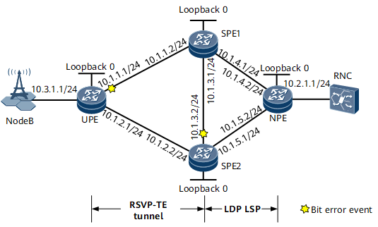
On the network shown in Figure 1, tunnel with TE hot standby protection configured needs to be deployed between the user-end provider edge (UPE) and SPE1 to carry L3VPN services. Bit-error-triggered RSVP-TE tunnel switching needs to be configured to protect services against bit errors. VPN FRR needs to be configured on the UPE, and VPNv4 FRR needs to be configured on the SPEs. If GE 0/1/1 on the UPE and GE 0/1/3 on SPE2 both encounter a bit error event, the primary and backup CR-LSPs of the RSVP-TE tunnel that carries the primary VPN route both enter the excessive BER state. As a result, bit-error-triggered RSVP-TE tunnel switching cannot protect services against bit errors. To resolve this problem, configure bit-error-triggered L3VPN route switching.
Device |
Interface |
IP Address |
|---|---|---|
UPE |
Loopback 0 |
1.1.1.1/32 |
GE 0/1/0 |
10.3.1.1/24 |
|
GE 0/1/1 |
10.1.1.1/24 |
|
GE 0/1/2 |
10.1.2.1/24 |
|
SPE1 |
Loopback 0 |
2.2.2.2/32 |
GE 0/1/1 |
10.1.1.2/24 |
|
GE 0/1/2 |
10.1.4.1/24 |
|
GE 0/1/3 |
10.1.3.1/24 |
|
SPE2 |
Loopback 0 |
3.3.3.3/32 |
GE 0/1/1 |
10.1.5.1/24 |
|
GE 0/1/2 |
10.1.2.2/24 |
|
GE 0/1/3 |
10.1.3.2/24 |
|
Network provider edge (NPE) |
Loopback 0 |
4.4.4.4/32 |
GE 0/1/1 |
10.1.5.2/24 |
|
GE 0/1/2 |
10.1.4.2/24 |
|
GE 0/1/3 |
10.2.1.1/24 |
Configuration Roadmap
The configuration roadmap is as follows:
Configure an IP address and a routing protocol for each interface so that all nodes can communicate at the network layer. This example uses Open Shortest Path First (OSPF) as the routing protocol.
Configure Multiprotocol Label Switching (MPLS) functions and public network tunnels. In this example, RSVP-TE tunnels are established between the UPE and SPEs, and Label Distribution Protocol (LDP) label switched paths (LSPs) are established between the NPE and SPEs.
Create a VPN instance on the UPE and NPE and import the local direct routes on the UPE and NPE to their respective VPN instance routing tables.
Establish Multiprotocol-Interior Border Gateway Protocol (MP-IBGP) peer relationships between the UPE and SPEs, and between the NPE and SPEs.
Configure SPEs as route reflectors (RRs) and specify the UPE and NPE as RR clients.
Configure VPN FRR on the UPE and VPNv4 FRR on the SPEs.
Configure bit-error-triggered RSVP-TE tunnel switching.
Configure bit-error-triggered L3VPN route switching.
Data Preparation
To complete the configuration, you need the following data:
Interface IP addresses listed in Table 1
Interior Gateway Protocol (IGP) protocol type (OSPF), process ID (1), and area ID (0)
Label switching router (LSR) IDs of the UPE and SPEs (1.1.1.1, 2.2.2.2, 3.3.3.3)
Tunnel interface names (Tunnel11), tunnel IDs (20), and tunnel interface addresses (loopback interface addresses) for the unidirectional tunnels between the UPE and SPE1 Tunnel interface names (Tunnel12), tunnel IDs (200), and tunnel interface addresses (loopback interface addresses) for the unidirectional tunnels between the UPE and SPE2 Tunnel policy names (policy1) for the unidirectional tunnels between the UPE and SPEs and tunnel selector names (BindTE) on the SPEs
Names (vpna), route distinguishers (RDs) (20:1), and VPN targets (1:1) of the VPN instances on the UPE and NPE
Procedure
- Configure interface IP addresses.
Assign an IP address to each interface according to Table 1 and create a loopback interface on each node. For configuration details, see Configuration Files in this section.
- Configure OSPF.
Configure OSPF on each node to allow the nodes to communicate at the network layer. For configuration details, see Configuration Files in this section.
- Enable Bidirectional Forwarding Detection (BFD) globally.
# Configure the UPE.
[~UPE] bfd
[*UPE-bfd] mpls-passive
[*UPE-bfd] commit
[~UPE-bfd] quit
Repeat this step for SPE1 and SPE2. For configuration details, see Configuration Files in this section.
- Configure MPLS functions and public network tunnels.
- Configure the egress of each unidirectional RSVP-TE tunnel to assign a non-null label to the penultimate hop.

This step is mandatory before you create an RSVP-TE tunnel. If this step is skipped, bit-error-triggered RSVP-TE tunnel switching cannot take effect.
# Configure the UPE.[~UPE] mpls [~UPE-mpls] label advertise non-null [*UPE-mpls] quit [*UPE] commit
# Configure SPE1.<SPE1> system-view [~SPE1] mpls [~SPE1-mpls] label advertise non-null [*SPE1-mpls] quit [*SPE1] commit
# Configure SPE2.<SPE2> system-view [~SPE2] mpls [~SPE2-mpls] label advertise non-null [*SPE2-mpls] quit [*SPE2] commit
- Configure the egress of each unidirectional RSVP-TE tunnel to assign a non-null label to the penultimate hop.
- Configure a VPN instance on the UPE and NPE.
# Configure the UPE.
[~UPE] ip vpn-instance vpna
[*UPE-vpn-instance-vpna] ipv4-family
[*UPE-vpn-instance-vpna-af-ipv4] route-distinguisher 20:1
[*UPE-vpn-instance-vpna-af-ipv4] vpn-target 1:1
[*UPE-vpn-instance-vpna-af-ipv4] quit
[*UPE-vpn-instance-vpna] quit
[*UPE] interface gigabitethernet 0/1/0
[*UPE-GigabitEthernet0/1/0] ip binding vpn-instance vpna
[*UPE-GigabitEthernet0/1/0] ip address 10.3.1.1 24
[*UPE-GigabitEthernet0/1/0] quit
[*UPE] bgp 20
[*UPE-bgp] ipv4-family vpn-instance vpna
[*UPE-bgp-vpna] import-route direct
[*UPE-bgp-vpna] quit
[*UPE-bgp] quit
[*UPE] commit
# Configure the NPE.
<NPE> system-view
[~NPE] ip vpn-instance vpna
[*NPE-vpn-instance-vpna] ipv4-family
[*NPE-vpn-instance-vpna-af-ipv4] route-distinguisher 20:1
[*NPE-vpn-instance-vpna-af-ipv4] vpn-target 1:1
[*NPE-vpn-instance-vpna-af-ipv4] quit
[*NPE-vpn-instance-vpna] quit
[*NPE] interface gigabitethernet 0/1/3
[*NPE-GigabitEthernet0/1/3] ip binding vpn-instance vpna
[*NPE-GigabitEthernet0/1/3] ip address 10.2.1.1 24
[*NPE-GigabitEthernet0/1/3] quit
[*NPE] bgp 20
[*NPE-bgp] ipv4-family vpn-instance vpna
[*NPE-bgp-vpna] import-route direct
[*NPE-bgp-vpna] quit
[*NPE-bgp] quit
[*NPE] commit
- Configure MP-IBGP peer relationships between the UPE and SPEs and between the NPE and SPEs.
# Configure the UPE.
[~UPE] bgp 20
[~UPE-bgp] router-id 1.1.1.1
[*UPE-bgp] peer 2.2.2.2 as-number 20
[*UPE-bgp] peer 2.2.2.2 connect-interface loopback 0
[*UPE-bgp] peer 3.3.3.3 as-number 20
[*UPE-bgp] peer 3.3.3.3 connect-interface loopback 0
[*UPE-bgp] ipv4-family vpnv4
[*UPE-bgp-af-vpnv4] peer 2.2.2.2 enable
[*UPE-bgp-af-vpnv4] peer 3.3.3.3 enable
[*UPE-bgp-af-vpnv4] quit
[*UPE-bgp] quit
[*UPE] commit
# Configure SPE1.
[~SPE1] bgp 20
[*SPE1-bgp] router-id 2.2.2.2
[*SPE1-bgp] peer 1.1.1.1 as-number 20
[*SPE1-bgp] peer 1.1.1.1 connect-interface loopback 0
[*SPE1-bgp] peer 3.3.3.3 as-number 20
[*SPE1-bgp] peer 3.3.3.3 connect-interface loopback 0
[*SPE1-bgp] peer 4.4.4.4 as-number 20
[*SPE1-bgp] peer 4.4.4.4 connect-interface loopback 0
[*SPE1-bgp] ipv4-family vpnv4
[*SPE1-bgp-af-vpnv4] undo policy vpn-target
[*SPE1-bgp-af-vpnv4] peer 1.1.1.1 enable
[*SPE1-bgp-af-vpnv4] peer 3.3.3.3 enable
[*SPE1-bgp-af-vpnv4] peer 4.4.4.4 enable
[*SPE1-bgp-af-vpnv4] quit
[*SPE1-bgp] quit
[*SPE1] commit
The configuration of SPE2 is similar to the configuration of SPE1. For configuration details, see Configuration Files in this section.
# Configure the NPE.
[~NPE] bgp 20
[~NPE-bgp] router-id 4.4.4.4
[*NPE-bgp] peer 2.2.2.2 as-number 20
[*NPE-bgp] peer 2.2.2.2 connect-interface loopback 0
[*NPE-bgp] peer 3.3.3.3 as-number 20
[*NPE-bgp] peer 3.3.3.3 connect-interface loopback 0
[*NPE-bgp] ipv4-family vpnv4
[*NPE-bgp-af-vpnv4] peer 2.2.2.2 enable
[*NPE-bgp-af-vpnv4] peer 3.3.3.3 enable
[*NPE-bgp-af-vpnv4] quit
[*NPE-bgp] quit
[*NPE] commit
- Configure SPEs as RRs and specify the UPE and NPE as RR clients.
# Configure SPE1.
[~SPE1] bgp 20
[~SPE1-bgp] ipv4-family vpnv4
[~SPE1-bgp-af-vpnv4] peer 1.1.1.1 reflect-client
[*SPE1-bgp-af-vpnv4] peer 1.1.1.1 next-hop-local
[*SPE1-bgp-af-vpnv4] peer 4.4.4.4 reflect-client
[*SPE1-bgp-af-vpnv4] peer 4.4.4.4 next-hop-local
[*SPE1-bgp-af-vpnv4] quit
[*SPE1-bgp] quit
[*SPE1] commit
The configuration of SPE2 is similar to the configuration of SPE1. For configuration details, see Configuration Files in this section.
- Apply the tunnel policy on the UPE and configure a tunnel selector on each SPE (because SPEs do not have VPN instances), so that the UPE and SPEs use RSVP-TE tunnels to transmit traffic.
# Configure the UPE.
[~UPE] ip vpn-instance vpna
[~UPE-vpn-instance-vpna] ipv4-family
[~UPE-vpn-instance-vpna-af-ipv4] route-distinguisher 20:1
[*UPE-vpn-instance-vpna-af-ipv4] tnl-policy policy1
[*UPE-vpn-instance-vpna-af-ipv4] quit
[*UPE-vpn-instance-vpna] quit
[*UPE] commit
# Configure SPE1.
[~SPE1] tunnel-selector bindTE permit node 10
[*SPE1-tunnel-selector] apply tunnel-policy policy1
[*SPE1-tunnel-selector] quit
[*SPE1] bgp 20
[*SPE1-bgp] ipv4-family vpnv4
[*SPE1-bgp-af-vpnv4] tunnel-selector bindTE
[*SPE1-bgp-af-vpnv4] quit
[*SPE1-bgp] quit
[*SPE1] commit
The configuration of SPE2 is similar to the configuration of SPE1. For configuration details, see Configuration Files in this section.
- Configure VPN FRR on the UPE and VPNv4 FRR on each SPE (VPN FRR cannot be configured on SPEs, because SPEs do not have VPN instances).
# Configure the UPE.
[~UPE] bgp 20
[~UPE-bgp] ipv4-family vpn-instance vpna
[~UPE-bgp-vpna] auto-frr
[*UPE-bgp-vpna] quit
[*UPE-bgp] quit
[*UPE] commit
# Configure SPE1.
[~SPE1] bgp 20
[~SPE1-bgp] ipv4-family vpnv4
[~SPE1-bgp-af-vpnv4] bestroute nexthop-resolved tunnel
[*SPE1-bgp-af-vpnv4] auto-frr
[*SPE1-bgp-af-vpnv4] quit
[*SPE1-bgp] quit
[*SPE1] commit
The configuration of SPE2 is similar to the configuration of SPE1. For configuration details, see Configuration Files in this section.
- Configure bit-error-triggered RSVP-TE tunnel switching.
# Configure the UPE.
[~UPE] interface Tunnel 11
[~UPE-Tunnel11] mpls te bit-error-detection
[*UPE-Tunnel11] mpls te reverse-lsp protocol rsvp-te ingress-lsr-id 2.2.2.2 tunnel-id 20
[*UPE-Tunnel11] quit
[*UPE] interface Tunnel 12
[*UPE-Tunnel12] mpls te bit-error-detection
[*UPE-Tunnel12] mpls te reverse-lsp protocol rsvp-te ingress-lsr-id 3.3.3.3 tunnel-id 200
[*UPE-Tunnel12] quit
[*UPE] commit
# Configure SPE1.
[~SPE1] interface Tunnel 11
[~SPE1-Tunnel11] mpls te bit-error-detection
[*SPE1-Tunnel11] mpls te reverse-lsp protocol rsvp-te ingress-lsr-id 1.1.1.1 tunnel-id 20
[*SPE1-Tunnel11] quit
[*SPE1] commit
# Configure SPE2.
[~SPE2] interface Tunnel 12
[~SPE2-Tunnel12] mpls te bit-error-detection
[*SPE2-Tunnel12] mpls te reverse-lsp protocol rsvp-te ingress-lsr-id 1.1.1.1 tunnel-id 200
[*SPE2-Tunnel12] quit
[*SPE2] commit
- Configure bit-error-triggered L3VPN route switching.
# Configure the UPE to reroute traffic when a bit error event occurs.
[~UPE] bgp 20
[~UPE-bgp] ipv4-family vpn-instance vpna
[~UPE-bgp-vpna] bestroute bit-error-detection
[*UPE-bgp-vpna] quit
[*UPE-bgp] quit
[*UPE] commit
# Configure SPE1 to decrease the local preference of the VPNv4 routes that it advertises to the NPE by 50 when a bit error event occurs.
[~SPE1] bgp 20
[~SPE1-bgp] ipv4-family vpnv4
[~SPE1-bgp-af-vpnv4] nexthop recursive-lookup bit-error-detection local-preference - 50
[*SPE1-bgp-af-vpnv4] quit
[*SPE1-bgp] quit
[*SPE1] commit
- Verify the configuration.
# After completing the configurations, run the display bgp vpnv4 vpn-instance vpna routing-table command on the UPE and NPE. The command output shows that the UPE and NPE both preferentially select the VPNv4 routes advertised by SPE1.
[~UPE] display bgp vpnv4 vpn-instance vpna routing-table
 BGP Local router ID is 1.1.1.1
 Status codes: * - valid, > - best, d - damped,
               h - history,  i - internal, s - suppressed, S - Stale
               Origin : i - IGP, e - EGP, ? - incomplete
 RPKI validation codes: V - valid, I - invalid, N - not-found

 VPN-Instance vpna, Router ID 1.1.1.1:


 Total Number of Routes: 4
      Network            NextHop        MED        LocPrf    PrefVal Path/Ogn

 *>   10.3.1.0/24       0.0.0.0         0                     0       ?
 *>   10.3.1.1/32       0.0.0.0         0                     0       ?
 *>i 10.2.1.0/24     2.2.2.2       0        20      0       ?
 * i                     3.3.3.3         0          20        0       ?
[~NPE] display bgp vpnv4 vpn-instance vpna routing-table
 BGP Local router ID is 4.4.4.4

 Status codes: * - valid, > - best, d - damped,
               h - history,  i - internal, s - suppressed, S - Stale
               Origin : i - IGP, e - EGP, ? - incomplete
 RPKI validation codes: V - valid, I - invalid, N - not-found

 VPN-Instance vpna, Router ID 4.4.4.4:


 Total Number of Routes: 4
      Network            NextHop        MED        LocPrf    PrefVal Path/Ogn

 *>i 10.3.1.0/24     2.2.2.2       0        20      0       ?
 * i                     3.3.3.3         0          20        0       ?
 *>   10.2.1.0/24       0.0.0.0         0                     0       ?
 *>   10.2.1.1/32       0.0.0.0         0                     0       ?
If GE 0/1/1 on the UPE and GE 0/1/3 on SPE2 both encounter a bit error event, the primary and backup CR-LSPs of the RSVP-TE tunnel that carries the primary VPN route both enter the excessive BER state. As a result, bit-error-triggered RSVP-TE tunnel switching cannot protect services against bit errors. In this situation, the UPE reroutes traffic. Meanwhile, SPE1 decreases the local preference of the VPNv4 routes that it advertises to the NPE by 50 after detecting the bit error event, so that the NPE preferentially selects the VPNv4 routes advertised by SPE2.
# Run the display bgp vpnv4 vpn-instance vpna routing-table command on the UPE. The command output shows that the UPE preferentially selects the VPNv4 routes advertised by SPE2. The VPNv4 routes advertised by SPE1 are not preferentially selected because of nexthop bit error.
[~UPE] display bgp vpnv4 vpn-instance vpna routing-table 10.2.1.0
 BGP local router ID : 1.1.1.1

 Local AS number : 20
 VPN-Instance vpna, Router ID 1.1.1.1:

 Paths:   2 available, 1 best, 1 select
 BGP routing table entry information of 10.2.1.0/24:
 Remote-Cross route
 Label information (Received/Applied): 4161/NULL
 From: 3.3.3.3 (3.3.3.3)
 Route Duration: 0d01h04m28s
 Relay Tunnel Out-Interface: Tunnel12
 Original nexthop: 3.3.3.3
 Qos information : 0x0
 Ext-Community: RT <1 : 1>
 AS-path Nil, origin incomplete, MED 0, localpref 20, pref-val 0, valid, internal, best, select, pre 255
 Originator: 4.4.4.4
 Cluster list: 3.3.3.3
 Not advertised to any peer yet

 BGP routing table entry information of 10.2.1.0/24:
 Remote-Cross route
 Label information (Received/Applied): 4161/NULL
 From: 2.2.2.2 (2.2.2.2)
 Route Duration: 0d01h04m28s
 Relay Tunnel Out-Interface: Tunnel11
 Original nexthop: 2.2.2.2
 Qos information : 0x0
 Ext-Community: RT <1 : 1>
 AS-path Nil, origin incomplete, MED 0, localpref 20, pref-val 0, valid, internal, pre 255, not preferred for nexthop bit error
 Originator: 4.4.4.4
 Cluster list: 2.2.2.2
 Not advertised to any peer yet
# Run the display bgp vpnv4 vpn-instance vpna routing-table command on the NPE. The command output shows that the NPE preferentially selects the VPNv4 routes advertised by SPE2. The VPNv4 routes advertised by SPE1 are not preferentially selected because of Local_Pref.
[~NPE] display bgp vpnv4 vpn-instance vpna routing-table 10.3.1.0
 BGP local router ID : 4.4.4.4

 Local AS number : 20
 VPN-Instance vpna, Router ID 4.4.4.4:

 Paths:   2 available, 1 best, 1 select
 BGP routing table entry information of 10.3.1.0/24:
 Remote-Cross route
 Label information (Received/Applied): 4162/NULL
 From: 3.3.3.3 (3.3.3.3)
 Route Duration: 0d00h19m21s
 Relay Tunnel Out-Interface: GigabitEthernet0/1/1
 Original nexthop: 3.3.3.3
 Qos information : 0x0
 Ext-Community: RT <1 : 1>
 AS-path Nil, origin incomplete, MED 0, localpref 20, pref-val 0, valid, internal, best, select, pre 255
 Originator: 1.1.1.1
 Cluster list: 3.3.3.3
 Not advertised to any peer yet

 BGP routing table entry information of 10.3.1.0/24:
 Remote-Cross route
 Label information (Received/Applied): 4162/NULL
 From: 2.2.2.2 (2.2.2.2)
 Route Duration: 0d00h19m21s
 Relay Tunnel Out-Interface: GigabitEthernet0/1/1
 Original nexthop: 2.2.2.2
 Qos information : 0x0
 Ext-Community: RT <1 : 1>
 AS-path Nil, origin incomplete, MED 0, localpref 50, pref-val 0, valid, internal, pre 255(original localpref 20), not preferred for Local_Pref
 Originator: 1.1.1.1
 Cluster list: 2.2.2.2
 Not advertised to any peer yet
Configuration Files
Configuration file of the UPE
#
sysname UPE
#
ip vpn-instance vpna
 ipv4-family
  route-distinguisher 20:1
  tnl-policy policy1
  vpn-target 1:1 export-extcommunity
  vpn-target 1:1 import-extcommunity
#
bfd
 mpls-passive
#
mpls lsr-id 1.1.1.1
#
mpls
 label advertise non-null
 mpls te
 mpls rsvp-te
 mpls te cspf
#
interface GigabitEthernet0/1/0
 undo shutdown
 ip binding vpn-instance vpna
 ip address 10.3.1.1 255.255.255.0
#
interface GigabitEthernet0/1/1
 undo shutdown
 ip address 10.1.1.1 255.255.255.0
 mpls
 mpls te
 mpls rsvp-te

#
interface GigabitEthernet0/1/2
 undo shutdown
 ip address 10.1.2.1 255.255.255.0
 mpls
 mpls te
 mpls rsvp-te

#
interface LoopBack0
 ip address 1.1.1.1 255.255.255.255
#
interface Tunnel11
 ip address unnumbered interface LoopBack0
 tunnel-protocol mpls te
 destination 2.2.2.2
 mpls te record-route
 mpls te backup hot-standby
 mpls te reserved-for-binding
 mpls te bit-error-detection
 mpls te reverse-lsp protocol rsvp-te ingress-lsr-id 2.2.2.2 tunnel-id 20
 mpls te tunnel-id 20
 mpls te bfd enable
#
interface Tunnel12
 ip address unnumbered interface LoopBack0
 tunnel-protocol mpls te
 destination 3.3.3.3
 mpls te record-route
 mpls te backup hot-standby
 mpls te reserved-for-binding
 mpls te bit-error-detection
 mpls te reverse-lsp protocol rsvp-te ingress-lsr-id 3.3.3.3 tunnel-id 200
 mpls te tunnel-id 200
 mpls te bfd enable
#
bgp 20
 router-id 1.1.1.1
 peer 2.2.2.2 as-number 20
 peer 2.2.2.2 connect-interface LoopBack0
 peer 3.3.3.3 as-number 20
 peer 3.3.3.3 connect-interface LoopBack0
 #
 ipv4-family unicast
  undo synchronization
  peer 2.2.2.2 enable
  peer 3.3.3.3 enable
 #
 ipv4-family vpnv4
  policy vpn-target
  peer 2.2.2.2 enable
  peer 3.3.3.3 enable
 #
 ipv4-family vpn-instance vpna
  bestroute bit-error-detection
  import-route direct
  auto-frr
#
ospf 1
 opaque-capability enable
 area 0.0.0.0
  network 1.1.1.1 0.0.0.0
  network 10.1.1.0 0.0.0.255
  network 10.1.2.0 0.0.0.255
  mpls-te enable
#
tunnel-policy policy1
 tunnel binding destination 2.2.2.2 te Tunnel11
 tunnel binding destination 3.3.3.3 te Tunnel12
#
return
Configuration file of SPE1
#
sysname SPE1
#
tunnel-selector bindTE permit node 10
 apply tunnel-policy policy1
#
bfd
 mpls-passive
#
mpls lsr-id 2.2.2.2
#
mpls
 label advertise non-null
 mpls te
 mpls rsvp-te
 mpls te cspf
#
mpls ldp
 #
 ipv4-family
#
interface GigabitEthernet0/1/1
 undo shutdown
 ip address 10.1.1.2 255.255.255.0
 mpls
 mpls te
 mpls rsvp-te

#
interface GigabitEthernet0/1/2
 undo shutdown
 ip address 10.1.4.1 255.255.255.0
 mpls
 mpls ldp
#
interface GigabitEthernet0/1/3
 undo shutdown
 ip address 10.1.3.1 255.255.255.0
 mpls
 mpls te
 mpls rsvp-te
 mpls ldp

#
interface LoopBack0
 ip address 2.2.2.2 255.255.255.255
#
interface Tunnel11
 ip address unnumbered interface LoopBack0
 tunnel-protocol mpls te
 destination 1.1.1.1
 mpls te record-route
 mpls te backup hot-standby
 mpls te reserved-for-binding
 mpls te bit-error-detection
 mpls te reverse-lsp protocol rsvp-te ingress-lsr-id 1.1.1.1 tunnel-id 20
 mpls te tunnel-id 20
 mpls te bfd enable
#
bgp 20
 router-id 2.2.2.2
 peer 1.1.1.1 as-number 20
 peer 1.1.1.1 connect-interface LoopBack0
 peer 3.3.3.3 as-number 20
 peer 3.3.3.3 connect-interface LoopBack0
 peer 4.4.4.4 as-number 20
 peer 4.4.4.4 connect-interface LoopBack0
 #
 ipv4-family unicast
  undo synchronization
  peer 1.1.1.1 enable
  peer 3.3.3.3 enable
  peer 4.4.4.4 enable
 #
 ipv4-family vpnv4
  undo policy vpn-target
  auto-frr
  nexthop recursive-lookup bit-error-detection local-preference - 50
  tunnel-selector bindTE
  bestroute nexthop-resolved tunnel
  peer 1.1.1.1 enable
  peer 1.1.1.1 reflect-client
  peer 1.1.1.1 next-hop-local
  peer 3.3.3.3 enable
  peer 4.4.4.4 enable
  peer 4.4.4.4 reflect-client
  peer 4.4.4.4 next-hop-local
#
ospf 1
 opaque-capability enable
 area 0.0.0.0
  network 2.2.2.2 0.0.0.0
  network 10.1.1.0 0.0.0.255
  network 10.1.3.0 0.0.0.255
  network 10.1.4.0 0.0.0.255
  mpls-te enable
#
tunnel-policy policy1
 tunnel binding destination 1.1.1.1 te Tunnel11
#
return
Configuration file of SPE2
#
sysname SPE2
#
tunnel-selector bindTE permit node 10
 apply tunnel-policy policy1
#
bfd
 mpls-passive
#
mpls lsr-id 3.3.3.3
#
mpls
 label advertise non-null
 mpls te
 mpls rsvp-te
 mpls te cspf
#
mpls ldp
 #
 ipv4-family
#
interface GigabitEthernet0/1/1
 undo shutdown
 ip address 10.1.5.1 255.255.255.0
 mpls
 mpls ldp
#
interface GigabitEthernet0/1/2
 undo shutdown
 ip address 10.1.2.2 255.255.255.0
 mpls
 mpls te
 mpls rsvp-te

#
interface GigabitEthernet0/1/3
 undo shutdown
 ip address 10.1.3.2 255.255.255.0
 mpls
 mpls te
 mpls rsvp-te
 mpls ldp

#
interface LoopBack0
 ip address 3.3.3.3 255.255.255.255
#
interface Tunnel12
 ip address unnumbered interface LoopBack0
 tunnel-protocol mpls te
 destination 1.1.1.1
 mpls te record-route
 mpls te backup hot-standby
 mpls te reserved-for-binding
 mpls te bit-error-detection
 mpls te reverse-lsp protocol rsvp-te ingress-lsr-id 1.1.1.1 tunnel-id 200
 mpls te tunnel-id 200
 mpls te bfd enable
#
bgp 20
 router-id 3.3.3.3
 peer 1.1.1.1 as-number 20
 peer 1.1.1.1 connect-interface LoopBack0
 peer 2.2.2.2 as-number 20
 peer 2.2.2.2 connect-interface LoopBack0
 peer 4.4.4.4 as-number 20
 peer 4.4.4.4 connect-interface LoopBack0
 #
 ipv4-family unicast
  undo synchronization
  peer 1.1.1.1 enable
  peer 2.2.2.2 enable
  peer 4.4.4.4 enable
 #
 ipv4-family vpnv4
  undo policy vpn-target
  auto-frr
  tunnel-selector bindTE
  bestroute nexthop-resolved tunnel
  peer 1.1.1.1 enable
  peer 1.1.1.1 reflect-client
  peer 1.1.1.1 next-hop-local
  peer 2.2.2.2 enable
  peer 4.4.4.4 enable
  peer 4.4.4.4 reflect-client
  peer 4.4.4.4 next-hop-local
#
ospf 1
 opaque-capability enable
 area 0.0.0.0
  network 3.3.3.3 0.0.0.0
  network 10.1.2.0 0.0.0.255
  network 10.1.3.0 0.0.0.255
  network 10.1.5.0 0.0.0.255
  mpls-te enable
#
tunnel-policy policy1
 tunnel binding destination 1.1.1.1 te Tunnel12
#
return
Configuration file of the NPE
#
sysname NPE
#
ip vpn-instance vpna
 ipv4-family
  route-distinguisher 20:1
  vpn-target 1:1 export-extcommunity
  vpn-target 1:1 import-extcommunity
#
mpls lsr-id 4.4.4.4
#
mpls
#
mpls ldp
 #
 ipv4-family
#
interface GigabitEthernet0/1/1
 undo shutdown
 ip address 10.1.5.2 255.255.255.0
 mpls
 mpls ldp
#
interface GigabitEthernet0/1/2
 undo shutdown
 ip address 10.1.4.2 255.255.255.0
 mpls
 mpls ldp
#
interface GigabitEthernet0/1/3
 undo shutdown
 ip binding vpn-instance vpna
 ip address 10.2.1.1 255.255.255.0
#
interface LoopBack0
 ip address 4.4.4.4 255.255.255.255
#
bgp 20
 router-id 4.4.4.4
 peer 2.2.2.2 as-number 20
 peer 2.2.2.2 connect-interface LoopBack0
 peer 3.3.3.3 as-number 20
 peer 3.3.3.3 connect-interface LoopBack0
 #
 ipv4-family unicast
  undo synchronization
  peer 2.2.2.2 enable
  peer 3.3.3.3 enable
 #
 ipv4-family vpnv4
  policy vpn-target
  peer 2.2.2.2 enable
  peer 3.3.3.3 enable
 #
 ipv4-family vpn-instance vpna
  import-route direct
#
ospf 1
 area 0.0.0.0
  network 4.4.4.4 0.0.0.0
  network 10.1.4.0 0.0.0.255
  network 10.1.5.0 0.0.0.255
#
return