Example for Configuring Bit-Error-Triggered PW Switching
This section provides an example for configuring bit-error-triggered pseudo wire (PW) switching.
Networking Requirements
On an IP radio access network (RAN), if a tunnel carries Layer 2 virtual private network (L2VPN) services, you can configure traffic engineering (TE) hot standby and pseudo wire (PW) redundancy to protect services. Bidirectional Forwarding Detection (BFD) for PW and BFD for label switched path (LSP), two commonly used detection mechanisms, can quickly trigger a link switchover after detecting a link fault. However, these detection mechanisms cannot trigger protection switching based on random bit errors caused by optical fiber aging or optical signal jitter. As a result, bit errors may degrade on an IP RAN or even interrupt services in extreme cases.
To resolve this problem, configure bit-error-triggered RSVP-TE tunnel switching and PW switching. If a bit error event occurs, the system first attempts to perform bit-error-triggered RSVP-TE tunnel switching. If the primary and backup constraint-based routed label switched paths (CR-LSPs) of the RSVP-TE tunnel are both in the excessive bit error rate (BER) state, bit-error-triggered RSVP-TE tunnel switching cannot protect services against bit errors. In this situation, the system performs bit-error-triggered PW switching to protect services against bit errors.
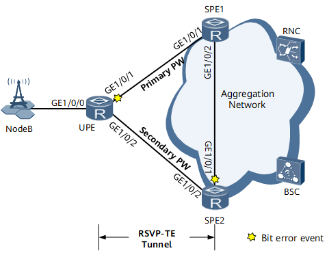
On the network shown in Figure 1, an RSVP-TE tunnel with TE hot standby protection needs to be deployed between the user-end provider edge (UPE) and SPE1 to carry L2VPN services. PW redundancy needs to be configured for the PW carried over the RSVP-TE tunnel. BFD for PW needs to be configured to achieve quick fault detection. If GE0/1/1 on the UPE and GE0/1/1 on SPE2 both encounter a bit error event, the primary and backup CR-LSPs of the RSVP-TE tunnel that carries the primary PW both enter the excessive BER state. As a result, bit-error-triggered RSVP-TE tunnel switching cannot protect services against bit errors. To resolve this problem, configure bit-error-triggered PW switching to divert traffic from the link that has encountered the bit error event.
Configuration Roadmap
The configuration roadmap is as follows:
Configure an IP address and a routing protocol for each interface so that all nodes can communicate at the network layer. This example uses Open Shortest Path First (OSPF) as the routing protocol.
Configure Multiprotocol Label Switching (MPLS) functions and public network tunnels. This example uses the RSVP-TE tunnels with TE hot standby protection between the UPE and SPEs as public network tunnels.
Configure the independent PW redundancy mode, which includes:
- Configure a remote MPLS Label Distribution Protocol (LDP) session between the UPE and each SPE.
- Configure a PW between the UPE and each SPE.
- Configure static BFD for PW.
- Configure SPE1 and SPE2 to belong to the same Virtual Router Redundancy Protocol (VRRP) backup group.
Configure bit-error-triggered protection switching, which includes:
- Enable bit-error-triggered RSVP-TE tunnel switching.
- Enable bit-error-triggered PW switching.
Data Preparation
To complete the configuration, you need the following data:
Interface IP addresses (see Figure 1)
Interior Gateway Protocol (IGP) protocol type (OSPF), process ID (100), and area ID (0)
Label switching router (LSR) IDs of the UPE and SPEs (1.1.1.1, 2.2.2.2, and 3.3.3.3)
Tunnel interface names (Tunnel11), tunnel IDs (100), and tunnel interface addresses (loopback interface addresses) for the unidirectional tunnels between the UPE and SPE1
Tunnel interface names (Tunnel12), tunnel IDs (200), and tunnel interface addresses (loopback interface addresses) for the unidirectional tunnels between the UPE and SPE2.
Names of the tunnel policies (policy1) on the UPE and SPEs
Virtual circuit (VC) IDs (1 and 2) of the PWs between the UPE and SPEs
Names of the static BFD sessions (master, pw1, and pw2) on the UPE and SPEs and the local and remote discriminators (2) of these BFD sessions
ID (20) and virtual IP address (10.1.3.111) of the VRRP group and priority (150) of the master VRRP device
Procedure
- Configure interface IP addresses.
Assign an IP address to each interface according to Figure 1 and create a loopback interface on each node. For configuration details, see Configuration Files in this section.
- Configure OSPF.
Configure OSPF on each node to allow the nodes to communicate at the network layer. For configuration details, see Configuration Files in this section.
- Configure MPLS functions and public network tunnels.
- Configure the egress of each unidirectional RSVP-TE tunnel to be created to assign a non-null label to the penultimate hop.

If you do not enable the egress to assign a non-null label to the penultimate hop before establishing a unidirectional RSVP-TE tunnel, bit-error-triggered RSVP-TE tunnel switching cannot take effect.
# Configure the UPE.[~UPE] mpls [~UPE-mpls] label advertise non-null [*UPE-mpls] quit [*UPE] commit
# Configure SPE1.[~SPE1] mpls [~SPE1-mpls] label advertise non-null [*SPE1-mpls] quit [*SPE1] commit
# Configure SPE2.[~SPE2] mpls [~SPE2-mpls] label advertise non-null [*SPE2-mpls] quit [*SPE2] commit
- Configure the egress of each unidirectional RSVP-TE tunnel to be created to assign a non-null label to the penultimate hop.
- Configure PWs.
- Configure a remote MPLS LDP session between the UPE and each SPE.
Pseudo wire emulation edge-to-edge (PWE3) uses extended LDP signaling to distribute VC labels. Because the UPE and SPEs communicate over RSVP-TE tunnels without using MPLS LDP, you must globally enable MPLS LDP on the UPE and SPEs and establish remote MPLS LDP sessions between them.
# Configure the UPE.
[~UPE] mpls ldp remote-peer 2.2.2.2
[*UPE-mpls-ldp-remote-2.2.2.2] remote-ip 2.2.2.2
[*UPE-mpls-ldp-remote-2.2.2.2] quit
[*UPE] mpls ldp remote-peer 3.3.3.3
[*UPE-mpls-ldp-remote-3.3.3.3] remote-ip 3.3.3.3
[*UPE-mpls-ldp-remote-3.3.3.3] quit
[*UPE] commit
# Configure SPE1.
[~SPE1] mpls ldp remote-peer 1.1.1.1
[*SPE1-mpls-ldp-remote-1.1.1.1] remote-ip 1.1.1.1
[*SPE1-mpls-ldp-remote-1.1.1.1] quit
[*SPE1] commit
# Configure SPE2.
[~SPE2] mpls ldp remote-peer 1.1.1.1
[*SPE2-mpls-ldp-remote-1.1.1.1] remote-ip 1.1.1.1
[*SPE2-mpls-ldp-remote-1.1.1.1] quit
[*SPE2] commit
- Configure a remote MPLS LDP session between the UPE and each SPE.
- Configure VRRP-based active/standby status negotiation for PWs.
# Configure SPE1.
[~SPE1] interface gigabitethernet 0/1/2
[~SPE1-GigabitEthernet0/1/2] vrrp vrid 20 virtual-ip 10.1.3.111
[*SPE1-GigabitEthernet0/1/2] admin-vrrp vrid 20 ignore-if-down
[*SPE1-GigabitEthernet0/1/2] vrrp vrid 20 priority 150
[*SPE1-GigabitEthernet0/1/2] quit
[*SPE1] interface virtual-ethernet 0/1/2.1
[*SPE1-Virtual-Ethernet0/1/2.1] mpls l2vc track admin-vrrp interface GigabitEthernet0/1/2 vrid 20 pw-redundancy
[*SPE1-Virtual-Ethernet0/1/2.1] quit
[*SPE1] commit
# Configure SPE2.
[~SPE2] interface gigabitethernet 0/1/1
[~SPE2-GigabitEthernet0/1/1] vrrp vrid 20 virtual-ip 10.1.3.111
[*SPE2-GigabitEthernet0/1/1] admin-vrrp vrid 20 ignore-if-down
[*SPE2-GigabitEthernet0/1/1] quit
[*SPE2] interface virtual-ethernet 0/1/1.1
[*SPE2-Virtual-Ethernet0/1/1.1] mpls l2vc track admin-vrrp interface GigabitEthernet0/1/1 vrid 20 pw-redundancy
[*SPE2-Virtual-Ethernet0/1/1.1] quit
[*SPE2] commit
# Run the display mpls l2vc command to check the status of the primary and secondary PWs. The command output shows that the primary PW is in the Active state.
[~UPE] display mpls l2vc
 total LDP VC : 2     2 up       0 down

 *client interface     : GigabitEthernet0/1/0.10 is up
  Administrator PW     : no
  session state        : up
  AC status            : up
  VC state             : up
  Label state          : 0
  Token state          : 0
  VC ID                : 1
  VC type              : VLAN
  destination          : 2.2.2.2
  local VC label       : 4212         remote VC label      : 4181
  control word         : enable
  remote control word    : disable
  forwarding entry     : exist
  local group ID       : 0
  remote group ID        : 0   local AC OAM State     : up   local PSN OAM State    : up   local forwarding state : forwarding   local status code      : 0x0   remote AC OAM state    : up   remote PSN OAM state   : up   remote forwarding state: forwarding   remote status code     : 0x0   ignore standby state   : no   BFD for PW             : unavailable   VCCV State             : up
  manual fault         : not set
  active state         : active
  OAM Protocol         : --
  OAM Status           : --
  OAM Fault Type       : --
  PW APS ID            : --
  PW APS Status        : --
  TTL Value            : 1
  link state           : up
  local VC MTU         : 1500         remote VC MTU        : 1500
  local VCCV             : alert ttl lsp-ping bfd   remote VCCV            : alert ttl lsp-ping bfd
  tunnel policy name   : policy1
  PW template name     : --
  primary or secondary : primary
  load balance type    : flow
  Access-port          : false
  Switchover Flag        : false   VC tunnel info         : 1 tunnels     NO.0  TNL type       : ldp   , TNL ID : 0x0000000001004c4e42
  create time          : 1 days, 8 hours, 8 minutes, 23 seconds
  up time              : 0 days, 9 hours, 15 minutes, 50 seconds
  last change time     : 0 days, 9 hours, 15 minutes, 50 seconds
  VC last up time      : 2013/01/29 04:29:14
  VC total up time     : 0 days, 9 hours, 15 minutes, 50 seconds
  CKey                 : 1
  NKey                 : 2415919356
  PW redundancy mode     : independent
  AdminPw interface    : --
  AdminPw link state   : --
  Forward state        : send inactive, receive inactive
  Diffserv Mode        : uniform
  Service Class        : --
  Color                : --
  DomainId             : --
  Domain Name          : --

 *client interface     : GigabitEthernet0/1/0.10 is up
  Administrator PW     : no
  session state        : up
  AC status            : up
  VC state             : up
  Label state          : 0
  Token state          : 0
  VC ID                : 2
  VC type              : VLAN
  destination          : 3.3.3.3
  local VC label       : 4213         remote VC label      : 4177
  control word         : enable
  remote control word    : disable
  forwarding entry     : exist
  local group ID       : 0
  remote group ID        : 0   local AC OAM State     : up   local PSN OAM State    : up   local forwarding state : forwarding   local status code      : 0x0   remote AC OAM state    : up   remote PSN OAM state   : up   remote forwarding state: forwarding   remote status code     : 0x0   ignore standby state   : no   BFD for PW             : unavailable   VCCV State             : up
  manual fault         : not set
  active state         : inactive
  OAM Protocol         : --
  OAM Status           : --
  OAM Fault Type       : --
  PW APS ID            : --
  PW APS Status        : --
  TTL Value            : 1
  link state           : up
  local VC MTU         : 1500         remote VC MTU        : 1500
  local VCCV             : alert ttl lsp-ping bfd   remote VCCV            : alert ttl lsp-ping bfd
  tunnel policy name   : policy1
  PW template name     : --
  primary or secondary : secondary
  load balance type    : flow
  Access-port          : false
  Switchover Flag        : false   VC tunnel info         : 1 tunnels     NO.0  TNL type       : ldp   , TNL ID : 0x0000000001004c4e43
  create time          : 1 days, 8 hours, 8 minutes, 23 seconds
  up time              : 0 days, 9 hours, 14 minutes, 52 seconds
  last change time     : 0 days, 9 hours, 14 minutes, 52 seconds
  VC last up time      : 2013/01/29 04:29:55
  VC total up time     : 1 days, 6 hours, 38 minutes, 42 seconds
  CKey                 : 2
  NKey                 : 2415919357
  PW redundancy mode     : independent
  AdminPw interface    : --
  AdminPw link state   : --
  Forward state        : send inactive, receive inactive
  Diffserv Mode        : uniform
  Service Class        : --
  Color                : --
  DomainId             : --
  Domain Name          : --
- Configure bit-error-triggered protection switching.
- Configure bit-error-triggered PW switching.
# Enable bit error detection on the attachment circuit (AC) interface of the UPE.
[~UPE] interface gigabitethernet 0/1/0.10
[~UPE-GigabitEthernet0/1/0.10] mpls l2vpn pw bit-error-detection
[*UPE-GigabitEthernet0/1/0.10] quit
[*UPE] commit
# Enable bit error detection on the AC interface of SPE1.
[~SPE1] interface virtual-ethernet 0/1/2.1
[~SPE1-Virtual-Ethernet0/1/2.1] mpls l2vpn pw bit-error-detection
[*SPE1-Virtual-Ethernet0/1/2.1] quit
[*SPE1] commit
# Enable bit error detection on the AC interface of SPE2.
[~SPE2] interface virtual-ethernet 0/1/1.1
[~SPE2-Virtual-Ethernet0/1/1.1] mpls l2vpn pw bit-error-detection
[*SPE2-Virtual-Ethernet0/1/1.1] quit
[*SPE2] commit
This example shows how to configure bit-error-triggered PW switching for single-segment PWs (SS-PWs). To configure bit-error-triggered PW switching for multi-segment PWs (MS-PWs), you must also run the mpls switch-l2vc ip-address vc-id between ip-address vc-id encapsulation encapsulation-type bit-error-detection command to enable bit error detection on SPEs.
- Configure bit-error-triggered PW switching.
- Verify the configuration.
# Run the display bfd bit-error-detection session all command. The command output shows bit error detection session information.
[~UPE] display bfd bit-error-detection session all
--------------------------------------------------------------------------------
BFD Bit Error Information:
--------------------------------------------------------------------------------
Session Type            : PE
FSM Board Id            : 9
Fault Type              : -
Min Tx Interval (ms)    : 1000
Max Tx Interval (ms)    : 30000
Actual Tx Interval (ms) : 30000
Detect Multi            : 3
Source IP Address       : 1.1.1.1
Destination IP Address  : 127.0.0.1
Destination Port        : 3784
TOS-EXP                 : 7
--------------------------------------------------------------------------------
LSP Information:
--------------------------------------------------------------------------------
Ingress LSR ID          : 1.1.1.1
Tunnel ID               : 100
LSP ID                  : 33
Tunnel-Interface        : Tunnel11
In-Interface            : GigabitEthernet0/1/1
Out-Interface           : GigabitEthernet0/1/1
LSP token               : 0x202
LSP Type                : Primary
--------------------------------------------------------------------------------
                 --------------------------------------------------------------------------------
BFD Bit Error Information:
--------------------------------------------------------------------------------
Session Type            : PE
FSM Board Id            : 9
Fault Type              : -
Min Tx Interval (ms)    : 1000
Max Tx Interval (ms)    : 30000
Actual Tx Interval (ms) : 30000
Detect Multi            : 3
Source IP Address       : 1.1.1.1
Destination IP Address  : 127.0.0.1
Destination Port        : 3784
TOS-EXP                 : 7
--------------------------------------------------------------------------------
LSP Information:
--------------------------------------------------------------------------------
Ingress LSR ID          : 1.1.1.1
Tunnel ID               : 200
LSP ID                  : 35
Tunnel-Interface        : Tunnel12
In-Interface            : GigabitEthernet0/1/2
Out-Interface           : GigabitEthernet0/1/2
LSP token               : 0x204
LSP Type                : Primary
--------------------------------------------------------------------------------
                 --------------------------------------------------------------------------------
BFD Bit Error Information:
--------------------------------------------------------------------------------
Session Type            : PE
FSM Board Id            : 9
Fault Type              : -
Min Tx Interval (ms)    : 1000
Max Tx Interval (ms)    : 30000
Actual Tx Interval (ms) : 30000
Detect Multi            : 3
Source IP Address       : 1.1.1.1
Destination IP Address  : 127.0.0.1
Destination Port        : 3784
TOS-EXP                 : 7
--------------------------------------------------------------------------------
LSP Information:
--------------------------------------------------------------------------------
Ingress LSR ID          : 1.1.1.1
Tunnel ID               : 100
LSP ID                  : 37
Tunnel-Interface        : Tunnel11
In-Interface            : GigabitEthernet0/1/2
Out-Interface           : GigabitEthernet0/1/2
LSP token               : 0x282
LSP Type                : Backup
--------------------------------------------------------------------------------
                 --------------------------------------------------------------------------------
BFD Bit Error Information:
--------------------------------------------------------------------------------
Session Type            : PE
FSM Board Id            : 9
Fault Type              : -
Min Tx Interval (ms)    : 1000
Max Tx Interval (ms)    : 30000
Actual Tx Interval (ms) : 30000
Detect Multi            : 3
Source IP Address       : 1.1.1.1
Destination IP Address  : 127.0.0.1
Destination Port        : 3784
TOS-EXP                 : 7
--------------------------------------------------------------------------------
LSP Information:
--------------------------------------------------------------------------------
Ingress LSR ID          : 1.1.1.1
Tunnel ID               : 200
LSP ID                  : 38
Tunnel-Interface        : Tunnel12
In-Interface            : GigabitEthernet0/1/1
Out-Interface           : GigabitEthernet0/1/1
LSP token               : 0x283
LSP Type                : Backup
--------------------------------------------------------------------------------
                      Total Session Number : 4
In this example, the BERs detected by GE0/1/1 on the UPE and GE0/1/1 on SPE2 exceeding the threshold for triggering an alarm indicating that a bit error event has occurred. As a result, the two GE interfaces reported a bit error event alarm. Consequently, the primary and backup CR-LSPs of the RSVP-TE tunnel are both in the excessive BER state, and bit-error-triggered RSVP-TE tunnel switching cannot protect services against bit errors. In this situation, the system performs bit-error-triggered PW switching to switch traffic from the primary PW to the secondary PW.
# Run the display mpls l2vc command on the UPE to check the status of the primary and secondary PWs. The command output shows that the secondary PW enters the Active state.
[~UPE] display mpls l2vc
 total LDP VC : 2     2 up       0 down

 *client interface     : GigabitEthernet0/1/0.10 is up
  Administrator PW     : no
  session state        : up
  AC status            : up
  VC state             : up
  Label state          : 0
  Token state          : 0
  VC ID                : 1
  VC type              : VLAN
  destination          : 2.2.2.2
  local VC label       : 4212         remote VC label      : 4181
  control word         : enable
  remote control word    : disable
  forwarding entry     : exist
  local group ID       : 0
  remote group ID        : 0   local AC OAM State     : up   local PSN OAM State    : up   local forwarding state : forwarding   local status code      : 0x0   remote AC OAM state    : up   remote PSN OAM state   : up   remote forwarding state: forwarding   remote status code     : 0x0   ignore standby state   : no   BFD for PW             : unavailable   VCCV State             : up
  manual fault         : not set
  active state         : inactive
  OAM Protocol         : --
  OAM Status           : --
  OAM Fault Type       : --
  PW APS ID            : --
  PW APS Status        : --
  TTL Value            : 1
  link state           : up
  local VC MTU         : 1500         remote VC MTU        : 1500
  local VCCV             : alert ttl lsp-ping bfd   remote VCCV            : alert ttl lsp-ping bfd
  tunnel policy name   : policy1
  PW template name     : --
  primary or secondary : primary
  load balance type    : flow
  Access-port          : false
  Switchover Flag        : true   VC tunnel info         : 1 tunnels     NO.0  TNL type       : ldp   , TNL ID : 0x0000000001004c4e42
  create time          : 1 days, 8 hours, 32 minutes, 54 seconds
  up time              : 0 days, 9 hours, 40 minutes, 21 seconds
  last change time     : 0 days, 9 hours, 40 minutes, 21 seconds
  VC last up time      : 2013/01/29 04:29:14
  VC total up time     : 0 days, 9 hours, 40 minutes, 21 seconds
  CKey                 : 1
  NKey                 : 2415919356
  PW redundancy mode     : independent
  AdminPw interface    : --
  AdminPw link state   : --
  Forward state        : send inactive, receive inactive
  Diffserv Mode        : uniform
  Service Class        : --
  Color                : --
  DomainId             : --
  Domain Name          : --

 *client interface     : GigabitEthernet0/1/0.10 is up
  Administrator PW     : no
  session state        : up
  AC status            : up
  VC state             : up
  Label state          : 0
  Token state          : 0
  VC ID                : 2
  VC type              : VLAN
  destination          : 3.3.3.3
  local VC label       : 4213         remote VC label      : 4177
  control word         : enable
  remote control word    : disable
  forwarding entry     : exist
  local group ID       : 0
  remote group ID        : 0   local AC OAM State     : up   local PSN OAM State    : up   local forwarding state : forwarding   local status code      : 0x0   remote AC OAM state    : up   remote PSN OAM state   : up   remote forwarding state: forwarding   remote status code     : 0x0   ignore standby state   : no   BFD for PW             : unavailable   VCCV State             : up
  manual fault         : not set
  active state         : active
  OAM Protocol         : --
  OAM Status           : --
  OAM Fault Type       : --
  PW APS ID            : --
  PW APS Status        : --
  TTL Value            : 1
  link state           : up
  local VC MTU         : 1500         remote VC MTU        : 1500
  local VCCV             : alert ttl lsp-ping bfd   remote VCCV            : alert ttl lsp-ping bfd
  tunnel policy name   : policy1
  PW template name     : --
  primary or secondary : secondary
  load balance type    : flow
  Access-port          : false
  Switchover Flag        : true   VC tunnel info         : 1 tunnels     NO.0  TNL type       : ldp   , TNL ID : 0x0000000001004c4e43
  create time          : 1 days, 8 hours, 32 minutes, 54 seconds
  up time              : 0 days, 9 hours, 39 minutes, 23 seconds
  last change time     : 0 days, 9 hours, 39 minutes, 23 seconds
  VC last up time      : 2013/01/29 04:29:55
  VC total up time     : 1 days, 7 hours, 3 minutes, 13 seconds
  CKey                 : 2
  NKey                 : 2415919357
  PW redundancy mode     : independent
  AdminPw interface    : --
  AdminPw link state   : --
  Forward state        : send inactive, receive inactive
  Diffserv Mode        : uniform
  Service Class        : --
  Color                : --
  DomainId             : --
  Domain Name          : --
Configuration Files
Configuration file of the UPE
#
sysname UPE
#
bfd
#
mpls lsr-id 1.1.1.1
#
mpls
 label advertise non-null
 mpls te
 mpls rsvp-te
 mpls te cspf
#
mpls l2vpn
#
mpls ldp
 #
 ipv4-family
#
mpls ldp remote-peer 2.2.2.2
 remote-ip 2.2.2.2
#
mpls ldp remote-peer 3.3.3.3
 remote-ip 3.3.3.3
#
interface GigabitEthernet0/1/0
 undo shutdown
#
interface GigabitEthernet0/1/0.10
 vlan-type dot1q 10
 mpls l2vc 2.2.2.2 1 tunnel-policy policy1 control-word
 mpls l2vc 3.3.3.3 2 tunnel-policy policy1 control-word secondary
 mpls l2vpn pw bit-error-detection
 mpls l2vpn redundancy independent
 mpls l2vpn stream-dual-receiving
#
interface GigabitEthernet0/1/1
 undo shutdown
 ip address 10.1.1.1 255.255.255.0
 mpls
 mpls te
 mpls rsvp-te

#
interface GigabitEthernet0/1/2
 undo shutdown
 ip address 10.1.2.1 255.255.255.0
 mpls
 mpls te
 mpls rsvp-te

#
interface LoopBack0
 ip address 1.1.1.1 255.255.255.255
#
interface Tunnel11
 ip address unnumbered interface LoopBack0
 tunnel-protocol mpls te
 destination 2.2.2.2
 mpls te record-route
 mpls te backup hot-standby
 mpls te reserved-for-binding
 mpls te bit-error-detection
 mpls te reverse-lsp protocol rsvp-te ingress-lsr-id 2.2.2.2 tunnel-id 100
 mpls te tunnel-id 100
#
interface Tunnel12
 ip address unnumbered interface LoopBack0
 tunnel-protocol mpls te
 destination 3.3.3.3
 mpls te record-route
 mpls te backup hot-standby
 mpls te reserved-for-binding
 mpls te bit-error-detection
 mpls te reverse-lsp protocol rsvp-te ingress-lsr-id 3.3.3.3 tunnel-id 200
 mpls te tunnel-id 200
#
ospf 100
 opaque-capability enable
 area 0.0.0.0
  network 1.1.1.1 0.0.0.0
  network 10.1.1.0 0.0.0.255
  network 10.1.2.0 0.0.0.255
  mpls-te enable
#
tunnel-policy policy1
 tunnel binding destination 2.2.2.2 te Tunnel11
 tunnel binding destination 3.3.3.3 te Tunnel12
#
bfd master bind pw interface GigabitEthernet0/1/0.10 remote-peer 2.2.2.2 pw-ttl auto-calculate
 discriminator local 2
 discriminator remote 2
#
return
Configuration file of SPE1
#
sysname SPE1
#
bfd
#
mpls lsr-id 2.2.2.2
#
mpls
 label advertise non-null
 mpls te
 mpls rsvp-te
 mpls te cspf
#
mpls l2vpn
#
mpls ldp
 #
 ipv4-family
#
mpls ldp remote-peer 1.1.1.1
 remote-ip 1.1.1.1
#
interface GigabitEthernet0/1/1
 undo shutdown
 ip address 10.1.1.2 255.255.255.0
 mpls
 mpls te
 mpls rsvp-te

#
interface GigabitEthernet0/1/2
 undo shutdown
 ip address 10.1.3.1 255.255.255.0
 vrrp vrid 20 virtual-ip 10.1.3.111
 admin-vrrp vrid 20 ignore-if-down
 vrrp vrid 20 priority 150
 mpls
 mpls te
 mpls rsvp-te

#
interface LoopBack0
 ip address 2.2.2.2 255.255.255.255
#
interface Virtual-Ethernet0/1/2
 ve-group 1 l2-terminate
#
interface Virtual-Ethernet0/1/2.1
 vlan-type dot1q 10
 mpls l2vc 1.1.1.1 1 tunnel-policy policy1 control-word
 mpls l2vc track admin-vrrp interface GigabitEthernet0/1/2 vrid 20 pw-redundancy
 mpls l2vpn pw bit-error-detection
#
interface Tunnel11
 ip address unnumbered interface LoopBack0
 tunnel-protocol mpls te
 destination 1.1.1.1
 mpls te record-route
 mpls te backup hot-standby
 mpls te reserved-for-binding
 mpls te bit-error-detection
 mpls te reverse-lsp protocol rsvp-te ingress-lsr-id 1.1.1.1 tunnel-id 100
 mpls te tunnel-id 100
#
bfd hello bind peer-ip 3.3.3.3 source-ip 2.2.2.2
 discriminator local 1005
 discriminator remote 1006
 commit
#
ospf 100
 opaque-capability enable
 graceful-restart
 area 0.0.0.0
  network 2.2.2.2 0.0.0.0
  network 10.1.1.0 0.0.0.255
  network 10.1.3.0 0.0.0.255
  mpls-te enable
#
tunnel-policy policy1
 tunnel binding destination 1.1.1.1 te Tunnel11
#
bfd pw1 bind pw interface Virtual-Ethernet0/1/2.1
 discriminator local 2
 discriminator remote 2
#
return
Configuration file of SPE2
#
sysname SPE2
#
bfd
#
mpls lsr-id 3.3.3.3
#
mpls
 label advertise non-null
 mpls te
 mpls rsvp-te
 mpls te cspf
#
mpls l2vpn
#
mpls ldp
 #
 ipv4-family
#
mpls ldp remote-peer 1.1.1.1
 remote-ip 1.1.1.1
#
interface GigabitEthernet0/1/1
 undo shutdown
 ip address 10.1.3.2 255.255.255.0
 vrrp vrid 20 virtual-ip 10.1.3.111
 admin-vrrp vrid 20 ignore-if-down
 mpls
 mpls te
 mpls rsvp-te

#
interface GigabitEthernet0/1/2
 undo shutdown
 ip address 10.1.2.2 255.255.255.0
 mpls
 mpls te
 mpls rsvp-te

#
interface LoopBack0
 ip address 2.2.2.2 255.255.255.255
#
interface Virtual-Ethernet0/1/1
 ve-group 1 l2-terminate
#
interface Virtual-Ethernet0/1/1.1
 vlan-type dot1q 10
 mpls l2vc 1.1.1.1 2 tunnel-policy policy1 control-word
 mpls l2vc track admin-vrrp interface GigabitEthernet0/1/1 vrid 20 pw-redundancy
 mpls l2vpn pw bit-error-detection
#
interface Tunnel12
 ip address unnumbered interface LoopBack0
 tunnel-protocol mpls te
 destination 1.1.1.1
 mpls te record-route
 mpls te backup hot-standby
 mpls te reserved-for-binding
 mpls te bit-error-detection
 mpls te reverse-lsp protocol rsvp-te ingress-lsr-id 1.1.1.1 tunnel-id 200
 mpls te tunnel-id 200
#
ospf 100
 opaque-capability enable
 area 0.0.0.0
  network 3.3.3.3 0.0.0.0
  network 10.1.2.0 0.0.0.255
  network 10.1.3.0 0.0.0.255
  mpls-te enable
#
tunnel-policy policy1
 tunnel binding destination 1.1.1.1 te Tunnel12
#
bfd pw2 bind pw interface Virtual-Ethernet0/1/1.1
 discriminator local 2
 discriminator remote 2
#
return