Configuring the Static VXLAN Active-Active Scenario
In the scenario where a data center is interconnected with an enterprise site, a CE is dual-homed to a VXLAN network. In this way, carriers can enhance VXLAN access reliability to improve the stability of user services so that rapid convergence can be implemented in case of a fault.
Context
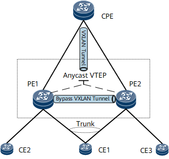
On the network shown in Figure 1, CE1 is dual-homed to PE1 and PE2. PE1 and PE2 use a virtual address as an NVE interface address at the network side, namely, an Anycast VTEP address. In this way, the CPE is aware of only one remote NVE interface. A VTEP address is configured on the CPE to establish a VXLAN tunnel with the Anycast VTEP address so that PE1, PE2, and the CPE can communicate.
The packets from the CPE can reach CE1 through either PE1 or PE2. However, single-homed CEs may exist, such as CE2 and CE3. As a result, after reaching a PE, the packets from the CPE may need to be forwarded by the other PE to a single-homed CE. Therefore, a bypass VXLAN tunnel needs to be established between PE1 and PE2.

Before an IPv6 network is used to transmit traffic between a CPE and PE, an IPv4 over IPv6 tunnel must be configured between them. To enable a VXLAN tunnel to recurse routes to the IPv4 over IPv6 tunnel, static routes must be configured on the CPE and PE, and the outbound interface of the route destined for the VXLAN tunnel's destination IP address must be set to the IPv4 over IPv6 tunnel interface.
Procedure
- Configure AC-side service access.
- Configure static VXLAN tunnels between the CPE and PEs. For configuration details, see Configuring a VXLAN Tunnel.
- Configure a bypass VXLAN tunnel between PE1 and PE2.
- Configure a VPN instance or EVPN instance.
Layer 2 communication (Configure an EVPN instance.)
- Run evpn vpn-instance vpn-instance-name bd-mode
A BD EVPN instance is created, and its view is displayed.
- Run route-distinguisher route-distinguisher
An RD is configured for the EVPN instance.
- Run vpn-target vpn-target &<1-8> [ both | export-extcommunity | import-extcommunity ]VPN targets are configured for the EVPN instance.
The export VPN target of the local end must be the same as the import VPN target of the remote end, and the import VPN target of the local end must be the same as the export VPN target of the remote end.
- Run quit
Exit the EVPN instance view.
- Run bridge-domain bd-id
The BD view is displayed.
- Run vxlan vni vni-id split-horizon-mode
A VNI is created and associated with the BD, and split horizon is applied to the BD.
- Run evpn binding vpn-instance vpn-instance-name [ bd-tag bd-tag ]
A specified EVPN instance is bound to the BD. By specifying different bd-tag, you can bind multiple BDs with different VLANs to the same EVPN instance and isolate services in the BDs.
- Run quit
Exit the BD view.
- Run commit
The configuration is committed.
- Run evpn vpn-instance vpn-instance-name bd-mode
Layer 3 communication (Configure a VPN instance.)
- Run ip vpn-instance vpn-instance-name
A VPN instance is created, and its view is displayed.
- Run ipv4-family [ unicast ]
The IPv4 address family is enabled for a VPN instance.
- Run route-distinguisher route-distinguisher
An RD is configured for the VPN instance.
- Run vpn-target vpn-target &<1-8> [ both | export-extcommunity | import-extcommunity ] [ evpn ]VPN targets are configured for the EVPN instance.
The export VPN target of the local end must be the same as the import VPN target of the remote end, and the import VPN target of the local end must be the same as the export VPN target of the remote end.
- Run quit
Exit the VPN instance ipv4-family view.
- Run quit
Exit the VPN instance view.
- Run bridge-domain bd-id
The BD view is displayed.
- Run vxlan vni vni-id split-horizon-mode
A VNI is created and associated with the BD, and split horizon is applied to the BD.
- Run quit
Exit the BD view.
- Run commit
The configuration is committed.
- Run ip vpn-instance vpn-instance-name
- Configure a VPN instance or EVPN instance.
- Configure FRR on the PEs.
Layer 2 communication
- Run evpn
The EVPN view is displayed.
- Run vlan-extend private enable
The function to add the VLAN private extended community attribute to routes to be sent to a peer is enabled.
- Run vlan-extend redirect enable
The function to redirect the received routes that carry the VLAN private extended community attribute is enabled.
- Run local-remote frr enable
Local-remote FRR is enabled.
- Run quit
Exit the EVPN view.
- Run commit
The configuration is committed.
- Run evpn
Layer 3 communication
- Run bgp as-number
The BGP view is displayed.
- Run ipv4-family vpn-instance vpn-instance-name
The BGP-VPN instance IPv4 address family is enabled, and its view is displayed.
- Run auto-frr
BGP auto FRR is enabled.
- Run peer { ipv4-address | group-name } enable
The function to exchange EVPN routes with a specified peer or peer group is enabled. The IP address is a CE address.
- Run advertise l2vpn evpn
The function to advertise EVPN IP prefix routes from a VPN instance is enabled.
- Run quit
Exit the BGP-VPN instance IPv4 address family view.
- Run quit
Exit the BGP view.
- Run commitcommit
The configuration is committed.
- Run bgp as-number
- (Optional) Configure a UDP port on the PEs to prevent the receiving of replicated packets.
- (Optional) Configure a VXLAN over IPsec tunnel between the CPE and PE to enhance the security for packets traversing an insecure network.
For configuration details, see the section Example for Configuring VXLAN over IPsec.
Verifying the Configuration
After configuring the VXLAN active-active scenario, verify information on the VXLAN tunnel, VNI status, and VBDIF. For details, see the section Verifying the Configuration of VXLAN in Distributed Gateway Mode Using BGP EVPN.