Configuring a DCI Scenario with a VLAN Base Accessing an MPLS EVPN IRB
In a DCI scenario, Ethernet sub-interfaces are associated with VLANs to access gateways or the DC network and the EVPN IRB function is enabled to allow the DCI network to carry Layer 2 or Layer 3 services.
Context
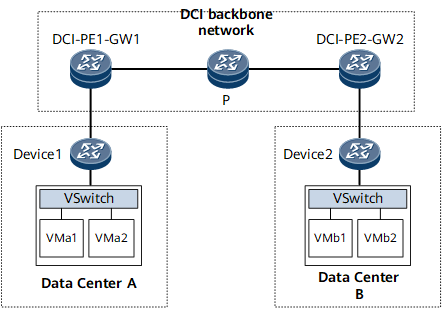
Centralized deployment mode: As shown in Figure 1, the DC gateway and the PE on the DCI backbone network are the same device (DCI-PE-GW). Specifically, the PE also functions as the DC gateway to access the DC network.
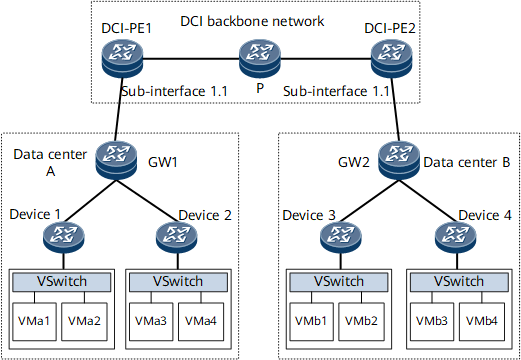
Distributed deployment mode: As shown in Figure 2, the DC gateway and PE (DCI-PE) are separately deployed, and DCI-PE takes the gateway as a CE. After Ethernet sub-interfaces and VBDIF interfaces are associated with VLANs to receive Layer 2 and Layer 3 service traffic, the traffic can be forwarded to other DCs over the DCI backbone network.
Pre-configuration Tasks
Before configuring a DCI scenario with a VLAN base accessing an MPLS EVPN IRB, complete the following task:
Configure Layer 3 route reachability on the IPv4 network.
Procedure
- Configure BGP EVPN peers.

If a BGP RR needs to be configured on the network, establish BGP EVPN peer relationships between all the PEs and the RR.
- (Optional) Run peer ipv4-address connect-interface interface-type interface-number [ ipv4-source-address ]
A source interface and a source IP address are specified to set up a TCP connection between the BGP peers.
When loopback interfaces are used to establish a BGP connection, it is recommended that the peer connect-interface command be run on both ends to ensure correct connection. If this command is run on only one end, the BGP connection may fail to be established.
- (Optional) Run peer ipv4-address connect-interface interface-type interface-number [ ipv4-source-address ]
- (Optional) Configure an L3VPN instance to store and manage received VM routes. You must perform this step if you want the network to carry Layer 3 services.
For IPv4 services, configure an IPv4 L3VPN instance.
Run ip vpn-instance vpn-instance-name
A VPN instance is created, and its view is displayed.
Run ipv4-family
The VPN instance IPv4 address family is created, and its view is displayed.
Run route-distinguisher route-distinguisher
An RD is set for the VPN instance IPv4 address family.
Run vpn-target vpn-target &<1-8> [ both | export-extcommunity | import-extcommunity ] evpn
One or multiple VPN targets are set for the VPN instance IPv4 address family.
-
The device is enabled to generate and advertise EVPN IP prefix routes and IRB routes.
(Optional) Run tnl-policy policy-name evpn
A specified tunnel policy is applied to the VPN instance IPv4 address family to associate the tunnel policy with the EVPN routes leaked to the VPN instance IPv4 address family.
(Optional) Run import route-policy policy-name evpn
An import route-policy is applied to the VPN instance IPv4 address family to filter EVPN routes to be imported to the VPN instance IPv4 address family. Perform this step to apply an import route-policy to the VPN instance IPv4 address family and set attributes for eligible EVPN routes. This enables the device to more precisely control EVPN routes to be imported into the VPN instance IPv4 address family more precisely.
(Optional) Run export route-policy policy-name evpn
An export route-policy is applied to the VPN instance IPv4 address family to filter EVPN routes to be advertised. Perform this step to apply an export route-policy to the VPN instance IPv4 address family and set attributes for eligible EVPN routes. This enables the device to more precisely control EVPN routes to be advertised.
Run quit
Exit the VPN instance IPv4 address family view.
Run quit
Exit the VPN instance view.
For IPv6 services, configure an IPv6 L3VPN instance.
Run ip vpn-instance vpn-instance-name
A VPN instance is created, and its view is displayed.
Run ipv6-family
The VPN instance IPv6 address family is created, and its view is displayed.
Run route-distinguisher route-distinguisher
An RD is set for the VPN instance IPv6 address family.
Run vpn-target vpn-target &<1-8> [ both | export-extcommunity | import-extcommunity ] evpn
One or multiple VPN targets are set for the VPN instance IPv6 address family.
-
The device is enabled to generate and advertise EVPN IP prefix routes and IRB routes.
(Optional) Run tnl-policy policy-name evpn
A specified tunnel policy is applied to the VPN instance IPv6 address family to associate the tunnel policy with the EVPN routes leaked to the VPN instance IPv6 address family.
(Optional) Run import route-policy policy-name evpn
An import route-policy is applied to the VPN instance IPv6 address family to filter EVPN routes to be imported to the VPN instance IPv6 address family. Perform this step to apply an import route-policy to the VPN instance IPv6 address family and set attributes for eligible EVPN routes. This enables the device to more precisely control EVPN routes to be imported into the VPN instance IPv6 address family.
(Optional) Run export route-policy policy-name evpn
An export route-policy is applied to the VPN instance IPv6 address family to filter EVPN routes to be advertised. Perform this step to apply an export route-policy to the VPN instance IPv6 address family and set attributes for eligible EVPN routes. This enables the device to more precisely control EVPN routes to be advertised.
Run quit
Exit the VPN instance IPv6 address family view.
Run quit
Exit the VPN instance view.
- Configure access-side interfaces.
If you want the network to carry both Layer 2 and Layer 3 services, perform the following configurations:
Run bridge-domain bd-id
The BD view is displayed.
Run evpn binding vpn-instance vpn-instance-name [ bd-tag bd-tag ]
The BD is bound to an EVPN instance. By specifying different bd-tag values, you can bind multiple BDs with different VLANs to the same EVPN instance and isolate services in the BDs.
Run quit
Return to the system view.
Run interface interface-type interface-number.subnum mode l2
A Layer 2 sub-interface is created, and its view is displayed.
Run encapsulation { dot1q [ vid low-pe-vid [ to high-pe-vid ] ] | untag | qinq [ vid pe-vid ce-vid { low-ce-vid [ to high-ce-vid ] | default } ] }
A traffic encapsulation type is configured, so that different interfaces can access different data packets.
Run rewrite pop { single | double }
The function to remove VLAN tags of received packets is enabled.
Run bridge-domain bd-id
The Layer 2 sub-interface is added to the BD, so that the sub-interface can transmit data packets through this BD.
Run quit
Return to the system view.
Run interface vbdif bd-id
A VBDIF interface is created, and its view is displayed.
Run ip binding vpn-instance vpn-instance-name
The VBDIF interface is bound to the VPN instance.
(Optional) Run ipv6 enable
IPv6 is enabled on the interface.
Run ip address ip-address { mask | mask-length } [ sub ] or ipv6 address { ipv6-address prefix-length | ipv6-address/prefix-length }
An IPv4/IPv6 address is configured for the VBDIF interface to implement Layer 3 interworking.
(Optional) Run mac-address mac-address
A MAC address is specified for the VBDIF interface.
Run vxlan anycast-gateway enable
The distributed gateway function is enabled.
After distributed gateway is enabled, the device discards the ARP packets received from the network side, learns only ARP packets from hosts on the user side, and generates host routes.
Run arp collect host enable or ipv6 nd collect host enable
Host information is collected.
Run quit
Return to the system view.
If you want the network to carry only Layer 2 services, perform the following configurations:
Run bridge-domain bd-id
The BD view is displayed.
Run evpn binding vpn-instance evpn-name [ bd-tag bd-tag ]
A specified EVPN instance is bound to the BD. By specifying different bd-tag values, you can bind multiple BDs with different VLANs to the same EVPN instance and isolate services in the BDs
Run quit
Return to the system view.
Run interface interface-type interface-number.subnum mode l2
A Layer 2 sub-interface is created, and its view is displayed.
Run encapsulation { dot1q [ vid low-pe-vid [ to high-pe-vid ] ] | untag | qinq [ vid pe-vid ce-vid { low-ce-vid [ to high-ce-vid ] | default } ] }
A traffic encapsulation type is configured, so that different interfaces can access different data packets.
Run rewrite pop { single | double }
The function to remove VLAN tags of received packets is enabled.
Run bridge-domain bd-id
The Layer 2 sub-interface is added to the BD, so that the sub-interface can transmit data packets through this BD.
Run quit
Return to the system view.
If you want the network to carry only Layer 3 services, see Binding Interfaces to a VPN Instance or Binding Interfaces to a IPv6 VPN Instance.
- Configure an EVPN instance in BD mode.
- (Optional) Configure an RR. To minimize the number of BGP EVPN peers on the network, deploy an RR so that the PEs establish BGP EVPN peer relationships only with the RR.
- Run commit
The configuration is committed.