Configuring Interworking Between a VPLS in PW Redundancy Mode and an Anycast VXLAN in an EVPN Active-Active Scenario
This section describes how to configure interworking to enable communication between an anycast VXLAN in an EVPN active-active scenario and a VPLS in PW redundancy mode configured.
Context
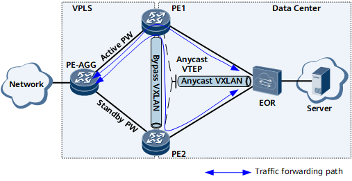
On the network shown in Figure 1, PE1 and PE2 are egress devices of the data center network. PE1 and PE2 work in active-active mode with a bypass VXLAN tunnel deployed between them. They use an anycast VTEP address to establish a VXLAN tunnel with the EOR. In this manner, PE1, PE2, and the EOR can communicate with each other. PE1 and PE2 communicate with the external network through the VPLS network, on which PW redundancy is configured. Specifically, the PE-AGG connects to PE1 and PE2 through primary and secondary PWs, respectively.
Configure VPLS PW redundancy on the PE-AGG, PE1, and PE2.
Configure the dynamic VXLAN active-active scenario on PE1 and PE2.
Configure the PWs connecting to the VPLS network to work in AC mode on PE1 and PE2. This configuration is required on the EVPN anycast VXLAN active-active network to prevent split horizon, which is configured on PE1 and PE2, from interrupting traffic. For details, see Procedure.
Procedure
- Run system-view
The system view is displayed.
- Run vsi vsi-name bd-mode
A VSI in BD mode is created. It's view is displayed.
- Run pwsignal ldp
LDP is configured as the PW signaling protocol, and the VSI-LDP view is displayed.
- Run vsi-id vsi-id
A VSI ID is configured.
- Run peer peer-address [ negotiation-vc-id vc-id ] [ encapsulation { ethernet | vlan } ] [ tnl-policy policy-name ] ac-mode
A PW is set to AC mode.
- Run commit
The configuration is committed.
Verifying the Interworking Configuration Between a Network with PW Redundancy and an EVPN Anycast VXLAN Active-Active Network
After configuring the interworking function, verify the configuration. For details, see Verifying the VXLAN Configuration and Verifying the VPLS PW Redundancy Configuration.