Configuring Interworking Between a VLL and a Common EVPN E-LAN
Traditional VLL is still used at the aggregation layer of a network, whereas the core network has evolved into EVPN. To allow communication between different layers, interworking between VLL and common EVPN E-LAN must be configured.
Context
As the MAN is evolving into EVPN, a large number of devices at the aggregation layer still use traditional VLLs, making E2E evolution into EVPN at a time difficult. However, the core network has evolved into EVPN. To implement communication between different network layers, VLL and common EVPN interworking must be supported.
On the network shown in Figure 1, CE1 with two sites attached is connected to a UPE through a NID (switch). The UPE and NPEs are connected through an MPLS network at the aggregation layer, and services are carried using a VLL. NPE1, NPE2, and NPE3 are connected through an MPLS network at the core layer, and services are carried through an EVPN.
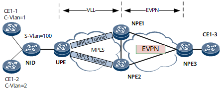
A UPE is dual-homed to NPE1 and NPE2, which improves access reliability. The UPE establishes the primary and secondary PWs with the master and slave NPEs, respectively. Traffic is sent through the primary PW, and the UPE is enabled to receive traffic through both the primary and secondary PWs.
On NPE1 and NPE2, the VLL is connected to the EVPN through PW VE interfaces. Specifically, the VLL is configured on the PW VE interfaces, and EVPN instances are bound to the PW VE sub-interfaces that are configured as QinQ VLAN tag termination sub-interfaces. In this manner, traffic is imported to the EVPN instances.
Pre-configuration Tasks
Before configuring interworking between VLL and a common EVPN E-LAN, complete the following tasks:
Configure interfaces and their IP addresses on the UPE, NPE1, NPE2, and NPE3.
Configure an IGP on the UPE, NPE1, NPE2, and NPE3 to implement route connectivity.
Configuring master/slave mode of PW redundancy on the UPE.
Configure EVPN functions on NPE3.
Procedure
- Configure basic EVPN functions on NPE1 and NPE2.
- Run mpls l2vpn
MPLS L2VPN is enabled on NPE1 and NPE2.
- Run quit
Return to the system view.
- Configure PW VE interfaces and sub-interfaces on NPE1 and NPE2. Bind the VLL to the PW VE interfaces and bind EVPN instances to the PW VE sub-interfaces.
- Run interface interface-type interface-number [ .subinterface-number ]
The PW VE sub-interface view is displayed.

Before running this command, ensure that the Layer 2 main interface does not have the port link-type dot1q-tunnel command configuration. If the configuration has existed, run the undo port link-type command to delete it.
- Run interface interface-type interface-number [ .subinterface-number ]
Verifying the Configuration
- Run the display evpn vpn-instance [ verbose ] command to view information about the EVPN instance-bound PW VE sub-interfaces.
- Run the display mpls l2vc [ vc-id | brief | interface interface-type interface-number | remote-info [ vc-id | unmatch | verbose ] | state { down | up } ] command to view the VLL-bound PW VE interfaces.