Configuring Interworking Between a VLL and an MPLS EVPN E-Line
The traditional VLL is still used at the aggregation layer of a network, whereas the core network has evolved into EVPN. To allow communication between different layers, VLL and MPLS EVPN E-Line interworking must be configured.
Context
As the MAN is evolving into EVPN, a large number of devices at the aggregation layer still use traditional VLLs, making E2E evolution into EVPN at a time difficult. However, the core network has evolved into EVPN. To implement communication between different network layers, VLL accessing EVPN must be supported. EVPN-VPWS services involve the E-Line and E-LAN models. This section describes how to configure interworking between a VLL and an MPLS EVPN E-Line.
On the network shown in Figure 1, CE1 with two sites attached is connected to a UPE through a NID (switch). The UPE and NPEs are connected through an MPLS network at the aggregation layer, and services are carried using a VLL. NPE1, NPE2, and NPE3 are connected through an MPLS network at the core layer, and services are carried through an EVPN.
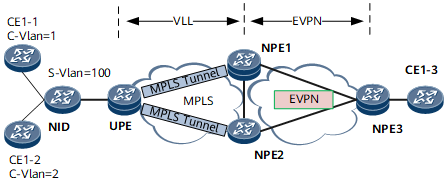
A UPE is dual-homed to NPE1 and NPE2, which improves access reliability. The UPE establishes the primary and secondary PWs with the master and slave NPEs, respectively. Traffic is sent through the primary PW, and the UPE is enabled to receive traffic through both the primary and secondary PWs.
On NPE1 and NPE2, the VLL is connected to the EVPN through PW VE interfaces. Specifically, the VLL is configured on the PW VE interfaces, and EVPN instances are bound to the PW VE sub-interfaces that are configured as QinQ VLAN tag termination sub-interfaces. In this manner, traffic is imported to the EVPN instances.
Pre-configuration Tasks
Before configuring interworking between a VLL and an MPLS EVPN E-Line, complete the following tasks:
Configure interfaces and their IP addresses on NPE1, NPE2, NPE3, and the UPE.
Configure an IGP on NPE1, NPE2, NPE3, and the UPE to implement Layer 3 reachability.
Configure PW redundancy in master/slave mode on the UPE.
Configuring EVPN VPWS over MPLS Functions on NPE1, NPE2, and NPE3.
Configure basic MPLS LDP functions on NPE1, NPE2, NPE3, and the UPE.
Configure an EVPL instance on each of NPE1, NPE2, and NPE3.
Perform the following steps on the NPE.
Procedure
- Run system-view
The system view is displayed.
- Run interface interface-type interface-number
The view of a main PW-VE interface is displayed.
- Run mpls l2vc { ip-address | pw-template template-name } * vc-id [ tunnel-policy policy-name [ endpoint endpoint-address color color-value ] | [ control-word | no-control-word ] | [ raw | tagged | ip-layer2 | ip-interworking ] | access-port | ignore-standby-state ] *
A dynamic VPWS connection is created.
- Run esi esi
An ESI is configured.
- Run quit
Return to the system view.
- Run interface interface-type interface-number.subnum
A PW-VE sub-interface is created, and the PW-VE sub-interface view is displayed.

Before running this command, ensure that the Layer 2 interface on which the PW-VE sub-interface is to be created does not have the port link-type dot1q-tunnel command configuration. If this configuration exists, run the undo port link-type command to delete the configuration.
In addition to a Layer 2 sub-interface, an Ethernet main interface, Layer 3 sub-interface, or Eth-Trunk interface can also function as an AC interface.
- Configure an encapsulation type for the PW-VE sub-interface.
- Run control-vid vid dot1q-termination [ rt-protocol ] or encapsulation dot1q-termination [ rt-protocol ]
The encapsulation type for a VLAN tag termination sub-interface is configured to be dot1q.
Specify rt-protocol so that the dot1q VLAN tag termination sub-interface supports routing protocols.
- Run either of the following commands:
- To configure a dot1q VLAN tag termination sub-interface, run the dot1q termination vid low-pe-vid [ vlan-group group-id ] command.
To configure a dot1q VLAN tag termination sub-interface and a matching policy for the sub-interface, run the dot1q termination vid low-pe-vid { 8021p { 8021p-value1 [ to val8021p2 ] } &<1-8> | dscp { valdscp1 [ to valdscp2 ] } &<1-10> | eth-type pppoe | default } [ vlan-group group-id ] command.
If you do not configure a matching policy, the dot1q VLAN tag termination sub-interface terminates the VLAN tags of packets carrying the specified VLAN ID. If you configure a matching policy, the sub-dot1q VLAN tag termination sub-interface terminates the VLAN tags of packets carrying the specified VLAN ID+802.1p value/DSCP value/EthType.
- Run control-vid vid dot1q-termination [ rt-protocol ] or encapsulation dot1q-termination [ rt-protocol ]
- Run evpl instance evpl-id
The PW-VE sub-interface is bound to the EVPL instance.
- Run commit
The configuration is committed.
Checking the Configurations
Run the display bgp evpn all routing-table command on the NPEs and check for EVI AD routes received by the NPEs.