Example for Configuring EVPN E-LAN over mLDP P2MP Tunnels
On a network where an EVPN carries multicast services, to reduce redundant traffic and conserve bandwidth resources, configure an EVPN E-LAN over mLDP P2MP tunnel for service transmission.
Networking Requirements
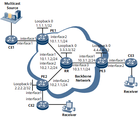
On the network shown in Figure 1, EVPN is configured on the PEs and used to carry multicast services. PE1 is the root node, and PE2 and PE3 are leaf nodes. The access side is the multicast source and the receiver. By default, an EVPN sends multicast service traffic from PE1 to PE2 and PE3 by means of ingress replication. Specifically, PE1 replicates a multicast packet into two copies and sends them to the P functioning as an RR. The P then sends one copy to PE2 and the other copy to PE3. For each additional receiver, an additional copy of the multicast packet is sent. This increases the volume of traffic on the link between PE1 and the P, consuming bandwidth resources. To conserve bandwidth resources, you can configure EVPN to use an mLDP P2MP tunnel to transmit multicast services. After the configuration is complete, PE1 sends only one copy of multicast traffic to the P. The P replicates the multicast traffic into copies and sends them to the leaf nodes, reducing the volume of traffic between PE1 and P.

Precautions
When you configure EVPN to use an mLDP P2MP tunnel for service transmission, note the following:
For the same EVPN instance, the export VPN target list of a site shares VPN targets with the import VPN target lists of the other sites. Conversely, the import VPN target list of a site shares VPN targets with the export VPN target lists of the other sites.
Using the local loopback interface address of each PE as the source address is recommended.
Configuration Roadmap
The configuration roadmap is as follows:
Configure an IGP on the backbone network to allow PEs and the RR to communicate.
Configure MPLS and mLDP P2MP both globally and per interface on each node of the backbone network.
Create an EVPN instance in BD mode and a BD on each PE, and bind the BD to the EVPN instance on each PE.
Configure a source address on each PE.
Configure each PE's sub-interface connecting to a CE.
Configure an ESI for each PE interface that connects to a CE.
Configure BGP EVPN peer relationships between the PEs and RR, and configure the PEs as RR clients.
Configure EVPN to use an mLDP P2MP tunnel for service transmission on each PE.
Data Preparation
To complete the configuration, you need the following data:
EVPN instance name: evrf1
EVPN instance evrf1's RD (100:1) and RT (1:1) on each PE
Procedure
- Assign an IP address to each interface on the RR and PEs according to Figure 1. For configuration details, see Configuration Files in this section.
- Configure an IGP on the backbone network to allow PEs and the RR to communicate. OSPF is used in this example.
# Configure PE1.
[~PE1] ospf 1
[*PE1-ospf-1] area 0
[*PE1-ospf-1-area-0.0.0.0] network 10.1.1.0 0.0.0.255
[*PE1-ospf-1-area-0.0.0.0] network 1.1.1.1 0.0.0.0
[*PE1-ospf-1-area-0.0.0.0] commit
[~PE1-ospf-1-area-0.0.0.0] quit
[~PE1-ospf-1] quit
# Configure PE2.
[~PE2] ospf 1
[*PE2-ospf-1] area 0
[*PE2-ospf-1-area-0.0.0.0] network 10.2.1.0 0.0.0.255
[*PE2-ospf-1-area-0.0.0.0] network 2.2.2.2 0.0.0.0
[*PE2-ospf-1-area-0.0.0.0] commit
[~PE2-ospf-1-area-0.0.0.0] quit
[~PE2-ospf-1] quit
# Configure PE3.
[~PE3] ospf 1
[*PE3-ospf-1] area 0
[*PE3-ospf-1-area-0.0.0.0] network 10.3.1.0 0.0.0.255
[*PE3-ospf-1-area-0.0.0.0] network 4.4.4.4 0.0.0.0
[*PE3-ospf-1-area-0.0.0.0] commit
[~PE3-ospf-1-area-0.0.0.0] quit
[~PE3-ospf-1] quit
# Configure the RR.
[~RR] ospf 1
[*RR-ospf-1] area 0
[*RR-ospf-1-area-0.0.0.0] network 10.1.1.0 0.0.0.255
[*RR-ospf-1-area-0.0.0.0] network 10.2.1.0 0.0.0.255
[*RR-ospf-1-area-0.0.0.0] network 10.3.1.0 0.0.0.255
[*RR-ospf-1-area-0.0.0.0] network 3.3.3.3 0.0.0.0
[*RR-ospf-1-area-0.0.0.0] commit
[~RR-ospf-1-area-0.0.0.0] quit
[~RR-ospf-1] quit
- Configure MPLS and mLDP P2MP both globally and per interface on each node of the backbone network and set up an mLDP P2MP tunnel.
# Configure PE1.
[~PE1] mpls lsr-id 1.1.1.1
[*PE1] mpls
[*PE1-mpls] quit
[*PE1] mpls ldp
[*PE1-mpls-ldp] mldp p2mp
[*PE1-mpls-ldp] quit
[*PE1] interface gigabitethernet 0/1/8
[*PE1-GigabitEthernet0/1/8] mpls
[*PE1-GigabitEthernet0/1/8] mpls ldp
[*PE1-GigabitEthernet0/1/8] commit
[~PE1-GigabitEthernet0/1/8] quit
# Configure PE2.
[~PE2] mpls lsr-id 2.2.2.2
[*PE2] mpls
[*PE2-mpls] quit
[*PE2] mpls ldp
[*PE2-mpls-ldp] mldp p2mp
[*PE2-mpls-ldp] quit
[*PE2] interface gigabitethernet 0/1/8
[*PE2-GigabitEthernet0/1/8] mpls
[*PE2-GigabitEthernet0/1/8] mpls ldp
[*PE2-GigabitEthernet0/1/8] commit
[~PE2-GigabitEthernet0/1/8] quit
# Configure the RR.
[~RR] mpls lsr-id 3.3.3.3
[*RR] mpls
[*RR-mpls] quit
[*RR] mpls ldp
[*RR-mpls-ldp] mldp p2mp
[*RR-mpls-ldp] quit
[*RR] interface gigabitethernet 0/1/0
[*RR-GigabitEthernet0/1/0] mpls
[*RR-GigabitEthernet0/1/0] mpls ldp
[*RR-GigabitEthernet0/1/0] quit
[*RR] interface gigabitethernet 0/1/8
[*RR-GigabitEthernet0/1/8] mpls
[*RR-GigabitEthernet0/1/8] mpls ldp
[*RR-GigabitEthernet0/1/8] quit
[*RR] interface gigabitethernet 0/1/16
[*RR-GigabitEthernet0/1/16] mpls
[*RR-GigabitEthernet0/1/16] mpls ldp
[*RR-GigabitEthernet0/1/16] commit
[~RR-GigabitEthernet0/1/16] quit
# Configure PE3.
[~PE3] mpls lsr-id 4.4.4.4
[*PE3] mpls
[*PE3-mpls] quit
[*PE3] mpls ldp
[*PE3-mpls-ldp] mldp p2mp
[*PE3-mpls-ldp] quit
[*PE3] interface gigabitethernet 0/1/0
[*PE3-GigabitEthernet0/1/0] mpls
[*PE3-GigabitEthernet0/1/0] mpls ldp
[*PE3-GigabitEthernet0/1/0] commit
[~PE3-GigabitEthernet0/1/0] quit
- Configure an EVPN instance on each PE.
# Configure PE1.
[~PE1] evpn vpn-instance evrf1 bd-mode
[*PE1-evpn-instance-evrf1] route-distinguisher 100:1
[*PE1-evpn-instance-evrf1] vpn-target 1:1
[*PE1-evpn-instance-evrf1] quit
[*PE1] bridge-domain 10
[*PE1-bd10] evpn binding vpn-instance evrf1
[*PE1-bd10] quit
[*PE1] commit
# Configure PE2.
[~PE2] evpn vpn-instance evrf1 bd-mode
[*PE2-evpn-instance-evrf1] route-distinguisher 100:1
[*PE2-evpn-instance-evrf1] vpn-target 1:1
[*PE2-evpn-instance-evrf1] quit
[*PE2] bridge-domain 10
[*PE2-bd10] evpn binding vpn-instance evrf1
[*PE2-bd10] quit
[*PE2] commit
# Configure PE3.
[~PE3] evpn vpn-instance evrf1 bd-mode
[*PE3-evpn-instance-evrf1] route-distinguisher 100:1
[*PE3-evpn-instance-evrf1] vpn-target 1:1
[*PE3-evpn-instance-evrf1] quit
[*PE3] bridge-domain 10
[*PE3-bd10] evpn binding vpn-instance evrf1
[*PE3-bd10] quit
[*PE3] commit
- Configure a source address on each PE.
# Configure PE1.
[~PE1] evpn source-address 1.1.1.1
[*PE1] commit
# Configure PE2.
[~PE2] evpn source-address 2.2.2.2
[*PE2] commit
# Configure PE3.
[~PE3] evpn source-address 4.4.4.4
[*PE3] commit
- Configure an Eth-Trunk sub-interface on each PE connecting to a CE.
# Configure PE1.
[~PE1] interface eth-trunk 10
[*PE1-Eth-Trunk10] quit
[*PE1] interface eth-trunk 10.1 mode l2
[*PE1-Eth-Trunk10.1] encapsulation dot1q vid 100
[*PE1-Eth-Trunk10.1] rewrite pop single
[*PE1-Eth-Trunk10.1] bridge-domain 10
[*PE1-Eth-Trunk10.1] quit
[*PE1] interface gigabitethernet 0/1/0
[*PE1-GigabitEthernet0/1/0] eth-trunk 10
[*PE1-GigabitEthernet0/1/0] quit
[*PE1] commit
# Configure PE2.
[~PE2] interface eth-trunk 10
[*PE2-Eth-Trunk10] quit
[*PE2] interface eth-trunk 10.1 mode l2
[*PE2-Eth-Trunk10.1] encapsulation dot1q vid 100
[*PE2-Eth-Trunk10.1] rewrite pop single
[*PE2-Eth-Trunk10.1] bridge-domain 10
[*PE2-Eth-Trunk10.1] quit
[*PE2] interface gigabitethernet 0/1/0
[*PE2-GigabitEthernet0/1/0] eth-trunk 10
[*PE2-GigabitEthernet0/1/0] quit
[*PE2] commit
# Configure PE3.
[~PE3] interface eth-trunk 10
[*PE3-Eth-Trunk10] quit
[*PE3] interface eth-trunk 10.1 mode l2
[*PE3-Eth-Trunk10.1] encapsulation dot1q vid 100
[*PE3-Eth-Trunk10.1] rewrite pop single
[*PE3-Eth-Trunk10.1] bridge-domain 10
[*PE3-Eth-Trunk10.1] quit
[*PE3] interface gigabitethernet 0/1/0
[*PE3-GigabitEthernet0/1/0] eth-trunk 10
[*PE3-GigabitEthernet0/1/0] quit
[*PE3] commit
- Configure an ESI for each PE interface that connects to a CE.
# Configure PE1.
[~PE1] interface eth-trunk 10
[*PE1-Eth-Trunk10] esi 0000.1111.1111.4444.5555
[*PE1-Eth-Trunk10] quit
[*PE1] commit
# Configure PE2.
[~PE2] interface eth-trunk 10
[*PE2-Eth-Trunk10] esi 0000.1111.2222.4444.5555
[*PE2-Eth-Trunk10] quit
[*PE2] commit
# Configure PE3.
[~PE3] interface eth-trunk 10
[*PE3-Eth-Trunk10] esi 0000.1111.3333.4444.5555
[*PE3-Eth-Trunk10] quit
[*PE3] commit
- Configure BGP EVPN peer relationships between the PEs and RR, and configure the PEs as RR clients.
# Configure PE1.
[~PE1] bgp 100
[*PE1-bgp] peer 3.3.3.3 as-number 100
[*PE1-bgp] peer 3.3.3.3 connect-interface loopback 0
[*PE1-bgp] l2vpn-family evpn
[*PE1-bgp-af-evpn] peer 3.3.3.3 enable
[*PE1-bgp-af-evpn] quit
[*PE1-bgp] quit
[*PE1] commit
# Configure PE2.
[~PE2] bgp 100
[*PE2-bgp] peer 3.3.3.3 as-number 100
[*PE2-bgp] peer 3.3.3.3 connect-interface loopback 0
[*PE2-bgp] l2vpn-family evpn
[*PE2-bgp-af-evpn] peer 3.3.3.3 enable
[*PE2-bgp-af-evpn] quit
[*PE2-bgp] quit
[*PE2] commit
# Configure PE3.
[~PE3] bgp 100
[*PE3-bgp] peer 3.3.3.3 as-number 100
[*PE3-bgp] peer 3.3.3.3 connect-interface loopback 0
[*PE3-bgp] l2vpn-family evpn
[*PE3-bgp-af-evpn] peer 3.3.3.3 enable
[*PE3-bgp-af-evpn] quit
[*PE3-bgp] quit
[*PE3] commit
# Configure the RR.
[~RR] bgp 100
[*RR-bgp] peer 1.1.1.1 as-number 100
[*RR-bgp] peer 1.1.1.1 connect-interface loopback 0
[*RR-bgp] peer 2.2.2.2 as-number 100
[*RR-bgp] peer 2.2.2.2 connect-interface loopback 0
[*RR-bgp] peer 4.4.4.4 as-number 100
[*RR-bgp] peer 4.4.4.4 connect-interface loopback 0
[*RR-bgp] l2vpn-family evpn
[*RR-bgp-af-evpn] peer 1.1.1.1 enable
[*RR-bgp-af-evpn] peer 1.1.1.1 reflect-client
[*RR-bgp-af-evpn] peer 2.2.2.2 enable
[*RR-bgp-af-evpn] peer 2.2.2.2 reflect-client
[*RR-bgp-af-evpn] peer 4.4.4.4 enable
[*RR-bgp-af-evpn] peer 4.4.4.4 reflect-client
[*RR-bgp-af-evpn] quit
[*RR-bgp] quit
[*RR] commit
After the configurations are complete, run the display bgp evpn peer command on the RR. The command output shows information about BGP peer relationships. In the following example, the output shows that BGP peer relationships are established between the PEs and RR and that they are in the Established state.
[~RR] display bgp evpn peer BGP local router ID : 10.1.1.2 Local AS number : 100 Total number of peers : 3 Peers in established state : 3 Peer V AS MsgRcvd MsgSent OutQ Up/Down State PrefRcv 1.1.1.1 4 100 231 253 0 03:07:26 Established 6 2.2.2.2 4 100 231 256 0 03:07:44 Established 6 4.4.4.4 4 100 232 254 0 03:07:54 Established 6 - Configure EVPN to use an mLDP P2MP tunnel for service transmission on each PE.
# Configure PE1.
[~PE1] evpn vpn-instance evrf1 bd-mode
[~PE1-evpn-instance-evrf1] inclusive-provider-tunnel
[*PE1-evpn-instance-evrf1-inclusive] root
[*PE1-evpn-instance-evrf1-inclusive-root] mldp p2mp
[*PE1-evpn-instance-evrf1-inclusive-root-mldpp2mp] root-ip 1.1.1.1
[*PE1-evpn-instance-evrf1-inclusive-root-mldpp2mp] quit
[*PE1-evpn-instance-evrf1-inclusive-root] quit
[*PE1-evpn-instance-evrf1-inclusive] quit
[*PE1-evpn-instance-evrf1] quit
[*PE1] commit
# Configure PE2.
[~PE2] evpn vpn-instance evrf1 bd-mode
[~PE2-evpn-instance-evrf1] inclusive-provider-tunnel
[*PE2-evpn-instance-evrf1-inclusive] leaf
[*PE2-evpn-instance-evrf1-inclusive-leaf] quit
[*PE2-evpn-instance-evrf1] quit
[*PE2] commit
# Configure PE3.
[~PE3] evpn vpn-instance evrf1 bd-mode
[~PE3-evpn-instance-evrf1] inclusive-provider-tunnel
[*PE3-evpn-instance-evrf1-inclusive] leaf
[*PE3-evpn-instance-evrf1-inclusive-leaf] quit
[*PE3-evpn-instance-evrf1] quit
[*PE3] commit
- Verify the configuration.
Run the display evpn vpn-instance name evrf1 inclusive-provider-tunnel verbose command on PE1. The command output shows information related to the root node.
[~PE1] display evpn vpn-instance name evrf1 inclusive-provider-tunnel verbose
 VPN-Instance Name and ID : evrf1, 3
  Address family bd-evpn
  Route Distinguisher : 100:1
  Label Policy        : label per bridge-domain
  Export VPN Targets  : 1:1
  Import VPN Targets  : 1:1
  Bridge-domain       : 10
  Ingress provider tunnel
    PMSI type      : P2MP mLDP
    Root ip        : 1.1.1.1
    Opaque value   : 01000400008001
    State          : up
  Egress provider tunnel
  Egress PMSI count: 0
Run the display evpn vpn-instance name evrf1 inclusive-provider-tunnel verbose command on PE2 or PE3. The command output shows information related to the leaf node. The following example uses the command output on PE2:
[~PE2] display evpn vpn-instance name evrf1 inclusive-provider-tunnel verbose
 VPN-Instance Name and ID : evrf1, 3
  Address family bd-evpn
  Route Distinguisher : 100:1
  Label Policy        : label per bridge-domain
  Export VPN Targets  : 1:1
  Import VPN Targets  : 1:1
  Bridge-domain       : 10
  Ingress provider tunnel
  Egress provider tunnel
  Egress PMSI count: 1
   *PMSI type      : P2MP mLDP
    Root ip        : 1.1.1.1
    Opaque value   : 01000400008001
    State          : up
Configuration Files
PE1 configuration file
#
sysname PE1
#
evpn vpn-instance evrf1 bd-mode
 route-distinguisher 100:1
 vpn-target 1:1 export-extcommunity
 vpn-target 1:1 import-extcommunity
 inclusive-provider-tunnel
  root
   mldp p2mp
    root-ip 1.1.1.1
#
mpls lsr-id 1.1.1.1
#
mpls
#
bridge-domain 10
 evpn binding vpn-instance evrf1
#
mpls ldp
 mldp p2mp
#
interface Eth-Trunk10
 esi 0000.1111.1111.4444.5555
#
interface Eth-Trunk10.1 mode l2
 encapsulation dot1q vid 100
 rewrite pop single
 bridge-domain 10
#
interface GigabitEthernet0/1/0
 undo shutdown
 eth-trunk 10
#
interface GigabitEthernet0/1/8
 undo shutdown
 ip address 10.1.1.1 255.255.255.0
 mpls
 mpls ldp
#
interface LoopBack0
 ip address 1.1.1.1 255.255.255.255
#
bgp 100
 peer 3.3.3.3 as-number 100
 peer 3.3.3.3 connect-interface LoopBack0
 #
 ipv4-family unicast
  undo synchronization
  peer 3.3.3.3 enable
 #
 l2vpn-family evpn
  undo policy vpn-target
  peer 3.3.3.3 enable
#
ospf 1
 area 0.0.0.0
  network 1.1.1.1 0.0.0.0
  network 10.1.1.0 0.0.0.255
#
evpn source-address 1.1.1.1
#
return
PE2 configuration file
#
sysname PE2
#
evpn vpn-instance evrf1 bd-mode
 route-distinguisher 100:1
 vpn-target 1:1 export-extcommunity
 vpn-target 1:1 import-extcommunity
 inclusive-provider-tunnel
  leaf
#
mpls lsr-id 2.2.2.2
#
mpls
#
bridge-domain 10
 evpn binding vpn-instance evrf1
#
mpls ldp
 mldp p2mp
#
interface Eth-Trunk10
 esi 0000.1111.2222.4444.5555
#
interface Eth-Trunk10.1 mode l2
 encapsulation dot1q vid 100
 rewrite pop single
 bridge-domain 10
#
interface GigabitEthernet0/1/0
 undo shutdown
 eth-trunk 10
#
interface GigabitEthernet0/1/8
 undo shutdown
 ip address 10.2.1.1 255.255.255.0
 mpls
 mpls ldp
#
interface LoopBack0
 ip address 2.2.2.2 255.255.255.255
#
bgp 100
 peer 3.3.3.3 as-number 100
 peer 3.3.3.3 connect-interface LoopBack0
 #
 ipv4-family unicast
  undo synchronization
  peer 3.3.3.3 enable
 #
 l2vpn-family evpn
  undo policy vpn-target
  peer 3.3.3.3 enable
#
ospf 1
 area 0.0.0.0
  network 2.2.2.2 0.0.0.0
  network 10.2.1.0 0.0.0.255
#
evpn source-address 2.2.2.2
#
return
PE3 configuration file
#
sysname PE3
#
evpn vpn-instance evrf1 bd-mode
 route-distinguisher 100:1
 vpn-target 1:1 export-extcommunity
 vpn-target 1:1 import-extcommunity
 inclusive-provider-tunnel
  leaf
#
mpls lsr-id 4.4.4.4
#
mpls
#
bridge-domain 10
 evpn binding vpn-instance evrf1
#
mpls ldp
 mldp p2mp
#
interface Eth-Trunk10
 esi 0000.1111.3333.4444.5555
#
interface Eth-Trunk10.1 mode l2
 encapsulation dot1q vid 100
 rewrite pop single
 bridge-domain 10
#
interface GigabitEthernet0/1/0
 undo shutdown
 eth-trunk 10
#
interface GigabitEthernet0/1/8
 undo shutdown
 ip address 10.3.1.2 255.255.255.0
 mpls
 mpls ldp
#
interface LoopBack0
 ip address 4.4.4.4 255.255.255.255
#
bgp 100
 peer 3.3.3.3 as-number 100
 peer 3.3.3.3 connect-interface LoopBack0
 #
 ipv4-family unicast
  undo synchronization
  peer 3.3.3.3 enable
 #
 l2vpn-family evpn
  undo policy vpn-target
  peer 3.3.3.3 enable
#
ospf 1
 area 0.0.0.0
  network 4.4.4.4 0.0.0.0
  network 10.3.1.0 0.0.0.255
#
evpn source-address 4.4.4.4
#
return
RR configuration file
#
sysname RR
#
mpls lsr-id 3.3.3.3
#
mpls
#
mpls ldp
 mldp p2mp
#
interface GigabitEthernet0/1/0
 undo shutdown
 ip address 10.1.1.2 255.255.255.0
 mpls
 mpls ldp
#
interface GigabitEthernet0/1/8
 undo shutdown
 ip address 10.2.1.2 255.255.255.0
 mpls
 mpls ldp
#
interface GigabitEthernet0/1/16
 undo shutdown
 ip address 10.3.1.1 255.255.255.0
 mpls
 mpls ldp
#
interface LoopBack0
 ip address 3.3.3.3 255.255.255.255
#
bgp 100
 peer 1.1.1.1 as-number 100
 peer 1.1.1.1 connect-interface LoopBack0
 peer 2.2.2.2 as-number 100
 peer 2.2.2.2 connect-interface LoopBack0
 peer 4.4.4.4 as-number 100
 peer 4.4.4.4 connect-interface LoopBack0
 #
 ipv4-family unicast
  undo synchronization
  peer 1.1.1.1 enable
  peer 2.2.2.2 enable
  peer 4.4.4.4 enable
 #
 l2vpn-family evpn
  undo policy vpn-target
  peer 1.1.1.1 enable
  peer 1.1.1.1 reflect-client
  peer 2.2.2.2 enable
  peer 2.2.2.2 reflect-client
  peer 4.4.4.4 enable
  peer 4.4.4.4 reflect-client
#
ospf 1
 area 0.0.0.0
  network 3.3.3.3 0.0.0.0
  network 10.1.1.0 0.0.0.255
  network 10.2.1.0 0.0.0.255
  network 10.3.1.0 0.0.0.255
#
return
CE1 configuration file
#
sysname CE1
#
bridge-domain 10
#
interface Eth-Trunk10
#
interface Eth-Trunk10.1 mode l2
 encapsulation dot1q vid 100
 bridge-domain 10
#
interface GigabitEthernet0/1/0
 undo shutdown
 eth-trunk 10
#
return
CE2 configuration file
#
sysname CE2
#
bridge-domain 10
#
interface Eth-Trunk10
#
interface Eth-Trunk10.1 mode l2
 encapsulation dot1q vid 100
 bridge-domain 10
#
interface GigabitEthernet0/1/0
 undo shutdown
 eth-trunk 10
#
return
CE3 configuration file
#
sysname CE3
#
bridge-domain 10
#
interface Eth-Trunk10
#
interface Eth-Trunk10.1 mode l2
 encapsulation dot1q vid 100
 bridge-domain 10
#
interface GigabitEthernet0/1/0
 undo shutdown
 eth-trunk 10
#
return