Configuring Interworking Between VPLS and MPLS EVPN E-LAN
On an IP RAN where VPLS is still used at the access layer but the aggregation network has evolved to MPLS EVPN, interworking between VPLS and MPLS EVPN E-LAN needs to be enabled.
Context
During IP RAN evolution towards EVPN, if VPLS is still commonly used on access-layer devices, it is difficult to implement E2E evolution towards MPLS EVPN. However, the aggregation network has already evolved to MPLS EVPN. In this case, the IP RAN needs to be configured with interworking between VPLS and MPLS EVPN E-LAN.
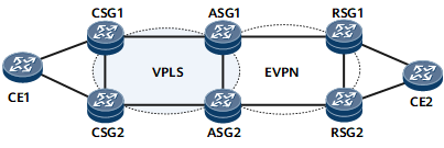
As shown in Figure 1, CSGs and ASGs are connected over the access network where the VPLS function is deployed to carry services, and ASGs and RSGs are connected over the aggregation network where the BD EVPN function is deployed to carry services. On ASGs, a BD needs to be configured and bound to a BD EVPN instance and a VSI to achieve interworking between VPLS and MPLS EVPN E-LAN.
Pre-configuration Tasks
Before configuring interworking between VPLS and MPLS EVPN E-LAN, complete the following tasks:
Configure LDP VPLS between CSGs and ASGs.
Configure BD EVPN between ASGs and RSGs.

Perform the following operations on each ASG:
Procedure
- Run system-view
The system view is displayed.
- Run evpn
The global EVPN configuration view is displayed.
- Run esi esi
The name of a static ESI instance is configured.
- Run evpn redundancy-mode single-active
The redundancy mode of the static ESI instance is set to single-active.
- Run quit
Return to the global EVPN configuration view.
- Run quit
Return to the system view.
- Run vsi vsi-name bd-mode
The VSI view is displayed.
- Run pwsignal ldp
LDP is configured as the PW signaling protocol, and the VSI-LDP view is displayed.
- Run vsi-id vsi-id
A VSI ID is configured.
- Configure a CSG as the UPE.
- Run peer peer-address [ negotiation-vc-id vc-id ] pw pw-name
A PW is created, and the VSI-LDP-PW view is displayed.
- Run esi esi
An ESI is configured for the PW interface.
The value of esi must be consistent with the name of the static ESI instance.
- (Optional) Run evpn e-tree-leaf
The leaf attributes of the PW interface are configured.
If users do not want the CE1-to-CSG1 traffic to be sent back to CSG2 and then CE1 over ASG1 and ASG2, users can configure leaf attributes for ASG1 and ASG2 in the VSI-LDP-PW view.
- Run quit
Return to the VSI-LDP view.
- Run quit
Return to the VSI view.
- Run quit
Return to the system view.
- Run bridge-domain bd-id
The BD view is displayed.
- Run l2 binding vsi vsi-name [ pw-tag pw-tag-value ]
The BD is bound to a VSI instance.
- Run evpn binding vpn-instance vpn-instance-name
The BD is bound to an EVPN instance.
- Run commit
The configuration is committed.
Verifying the Configuration
Run the display bgp evpn { all | route-distinguisher route-distinguisher | vpn-instance vpn-instance-name } routing-table { ad-route | es-route | inclusive-route | mac-route | prefix-route } prefix command on an ASG to view details about BGP EVPN routes, including information about access-side PWs.
Run the display evpn vpn-instance name vpn-instance-name df result [ esi esi ] command on an ASG to view the DF election result of an EVPN instance, including information about access-side PWs.