Configuring NFVI Distributed Gateway (Asymmetric Mode)
In the Network Function Virtualization Infrastructure (NFVI) telco cloud solution, the NFVI distributed gateway function enables UE traffic to pass through the data center network (DCN) and be processed by the virtualized unified gateway (vUGW) and virtual multiservice engine (vMSE). In addition, traffic can be balanced during internal transmission over the DCN.
Usage Scenario
Huawei's NFVI telco cloud solution incorporates Data Center Interconnect (DCI) and DCN solutions. A large volume of UE traffic enters the DCN and accesses its vUGW and vMSE. After being processed by the vUGW and vMSE, the UE traffic is forwarded over the Internet through the DCN to the destination devices. Equally, response traffic sent over the Internet from the destination devices to the UEs also undergoes this process. For this to take place and to ensure that the traffic is balanced within the DCN, you need to deploy the NFVI distributed gateway function on the DCN.
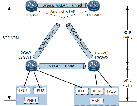
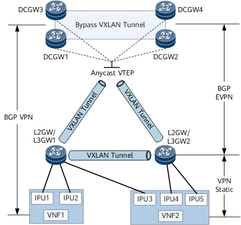
Figure 1 or Figure 2 shows the network of NFVI distributed gateways. DC gateways are the boundary gateways of the DCN and can be used to exchange routes with the external network. L2GW/L3GW1 and L2GW/L3GW2 are connected to virtualized network functions (VNFs). VNF1 and VNF2 can be deployed as virtualized NEs to implement the vUGW and vMSE functions and connected to the L2GW/L3GW1 and L2GW/L3GW2 through the interface processing unit (IPU).
The VXLAN active-active /quad-active gateway function is deployed on DCGW1 and DCGW2. Specifically, a bypass VXLAN tunnel is established between DC gateways and these DC gateways use the same virtual anycast VTEP address to establish VXLAN tunnels with L2GW/L3GW1 and L2GW/L3GW2.
The distributed gateway function is deployed on L2GW/L3GW1 and L2GW/L3GW2, and a VXLAN tunnel is established between L2GW/L3GW1 and L2GW/L3GW2.

The deployment method of the VXLAN quad-active gateway function is similar to that of the VXLAN active-active gateway function. If you want to deploy the VXLAN quad-active gateway function on DC gateways, see Configuring the Dynamic VXLAN Active-Active Scenario.
Establish a VPN BGP peer relationship between each VNF and DC gateway, so that VNFs can advertise UE routes to DC gateways.
Configure static VPN routes on L2GW/L3GW1 and L2GW/L3GW2 for them to communicate with VNFs. The routes' destination IP addresses are the VNFs' IP addresses, and the next hops are the IP addresses of the IPUs.
Establish a BGP EVPN peer relationship between any two of the DC gateways and L2GWs/L3GWs (full-mesh), so that an L2GW/L3GW can flood static routes destined for the VNFs to other devices through BGP EVPN peer relationships, and a DC gateway can advertise local loopback routes and default routes to L2GWs/L3GWs through the BGP EVPN peer relationships.
Traffic between a UE and the Internet that is forwarded through a VNF is called north-south traffic, whereas the traffic between VNF1 and VNF2 is called east-west traffic. To balance both of these, you need to configure load balancing on DC gateways and L2GWs/L3GWs.
The NFVI distributed gateway function is supported for both IPv4 and IPv6 services. If a configuration step is not differentiated in terms of IPv4 and IPv6, this step applies to both IPv4 and IPv6 services.
When the NFVI distributed gateway is used, the NetEngine 8000 F functions as either a DC gateway or an L2GW/L3GW. However, if the NetEngine 8000 F is used as an L2GW/L3GW, east-west traffic cannot be balanced.
Pre-configuration Tasks
Before configuring NFVI distributed gateway, complete the following tasks:
Configure the static VXLAN active-active scenario or configure the dynamic VXLAN active-active scenario on each DC gateway and each L2GW/L3GW.
Complete the configurations described in Configuring VXLAN in Distributed Gateway Mode Using BGP EVPN on each L2GW/L3GW.
Configure static routes to VNF1 and VNF2 on each L2GW/L3GW. For configuration details, see Creating IPv4 Static Routes or Creating IPv6 Static Routes.
- Configuring an L3VPN Instance on a DCGW
- You can configure an L3VPN instance to store and manage received mobile phone routes and VPN routes reachable to VNFs.
- Configuring Route Advertisement on a DC-GW
- After route advertisement is configured on a DC-GW, the DC-GW can construct its own forwarding entries based on received EVPN or BGP routes.
- Configuring Route Advertisement on an L2GW/L3GW
- After route advertisement is configured on an L2GW/L3GW, the L2GW/L3GW can construct its own forwarding entries based on received EVPN or BGP routes.
- Configuring Load Balancing
- You must configure load balancing to balance traffic over a DCN.
- Verifying the NFVI Distributed Gateway Configuration
- After configuring the NFVI distributed gateway function, verify the configuration.