Configuring Interworking Between VPLS and EVPN VPLS over SRv6
When a conventional VPLS network and an EVPN VPLS over SRv6 network are converged, you need to configure interworking between VPLS and EVPN VPLS over SRv6.
Context
Conventional L2VPNs use VPLS over MPLS to implement Layer 2 communication. Compared with VPLS, EVPN, a next-generation VPN technology, provides many advantages, such as multi-homing, all-active, and control plane-based MAC address learning. Especially, EVPN over SRv6 can accommodate the growth of IPv6 networks and 5G services. Therefore, VPLS over MPLS is gradually evolving to EVPN over SRv6. However, the live network with a large number of existing VPLS services cannot be upgraded to EVPN VPLS over SRv6 at a time. In this case, you can configure interworking between VPLS and EVPN VPLS over SRv6 to support service convergence.
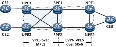
In Figure 1, VPLS over MPLS is deployed between UPEs and SPEs to carry services; EVPN VPLS over SRv6 is deployed between SPEs and NPEs to carry services. You need to configure SPE1 and SPE2 for interworking between VPLS and EVPN VPLS over SRv6.
Pre-configuration Tasks
Before configuring interworking between VPLS and EVPN VPLS over SRv6, complete the following tasks:
Configure LDP VPLS between UPEs and SPEs.
Complete the task of Configuring EVPN VPLS over SRv6 BE or Configuring EVPN VPLS over SRv6 TE Policy between an SPE and an NPE.

Perform the following steps on SPE1 and SPE2.
Procedure
- Run system-view
The system view is displayed.
- Run evpn
The global EVPN configuration view is displayed.
- Run esi esi
The name of a static ESI instance is configured.
- Run evpn redundancy-mode single-active
The redundancy mode of the static ESI instance is set to single-active.
- Run quit
Return to the global EVPN configuration view.
- Run quit
Return to the system view.
- Run vsi vsi-name bd-mode
The VSI view is displayed.
- Run pwsignal ldp
LDP is configured as a PW signaling protocol, and the VSI-LDP view is displayed.
- Run vsi-id vsi-id
A VSI ID is set.
- Run peer peer-address [ negotiation-vc-id vc-id ] [ tnl-policy policy-name ] upe
A UPE is configured as a peer.
- Run peer peer-address [ negotiation-vc-id vc-id ] pw pw-name
A PW is created, and the VSI-LDP-PW view is displayed.
- Run esi esi
An ESI is set for the PW interface. The ESI value must be the same as the name of the static ESI instance.
- (Optional) Run evpn e-tree-leaf
The leaf attribute is configured for the PW interface. If you do not want CE1-to-UPE1 traffic is looped back to CE1 through SPE1 and SPE2, configure the leaf attribute in the VSI-LDP-PW views of SPE1 and SPE2.
- Run quit
Return to the VSI-LDP view.
- Run quit
Return to the VSI view.
- Run quit
Return to the system view.
- Run bridge-domain bd-id
The BD view is displayed.
- Run l2 binding vsi vsi-name [ pw-tag pw-tag-value ]
The BD is bound to the VSI.
- Run evpn binding vpn-instance vpn-instance-name
The BD is bound to the EVPN instance.
- Run commit
The configuration is committed.
Verifying the Configuration
Run the display bgp evpn { all | route-distinguisher route-distinguisher | vpn-instance vpn-instance-name } routing-table { ad-route | es-route | inclusive-route | mac-route | prefix-route } prefix command to check detailed information about BGP EVPN routes, including access-side PW information.
Run the display evpn vpn-instance name vpn-instance-name df result [ esi esi command to check the DF election results, including information about the access-side PW.