Fundamentals of EVPN Seamless MPLS
EVPN seamless MPLS establishes a BGP LSP across the access, aggregation, and core layers and transmits services along this BGP LSP in E2E mode. Service traffic can be transmitted between any two points over the LSP. The EVPN seamless MPLS network architecture maximizes service scalability using the following functions:
- Allows access nodes to signal all services to an LSP.
- Uses the same transport layer convergence technology to converge services in case of any network-side faults, without affecting service transmission.
Background
The popularity of EVPN MPLS networks poses increasing requirements for the service scalability of the network architecture. The different metro networks of a service provider or the collaborative backbone networks of different service providers often span multiple ASs. In this case, EVPN seamless MPLS can be used to establish an inter-AS E2E BGP LSP to carry EVPN services.
Implementation
On a seamless MPLS network, the EVPN services to be transmitted need to be encapsulated using signaling only at service access points. In addition, if a network-side fault triggers EVPN service convergence, the same transport layer convergence technology is used to converge the services, without the service layer being aware of the fault.
Application Scenarios
EVPN seamless MPLS supports the following networking solutions:
- EVPN intra-AS seamless MPLS: The access, aggregation, and core layers are deployed within a single AS. This solution mainly applies to mobile transport networks.
- EVPN inter-AS seamless MPLS: The access and aggregation layers are deployed in a single AS, whereas the core layer is deployed in a different AS. This solution mainly applies to enterprise networks.
EVPN Intra-AS Seamless MPLS
Network Deployment |
Description |
|
|---|---|---|
Control plane |
Deploying routing protocols |
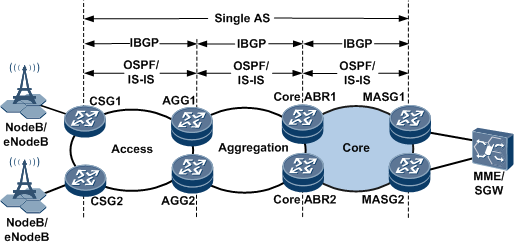
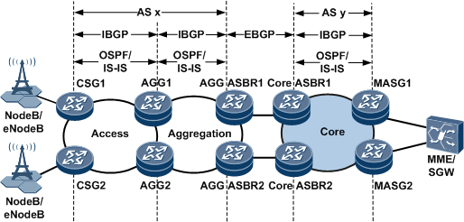
In Figure 1, routing protocol deployment on devices is as follows:
|
BGP EVPN peer relationship establishment and route advertisement |
As shown in Figure 1, AGGs and core ABRs function as RRs. BGP EVPN peer relationships need to be established between CSGs and AGGs, between MASGs and core ABRs, and between AGGs and core ABRs. Then, EVPN MAC/IP routes (Type 2) and IP prefix routes (Type 5) need to be transmitted between the peers to transmit MAC and IP routing information. |
|
Deploying tunnels |
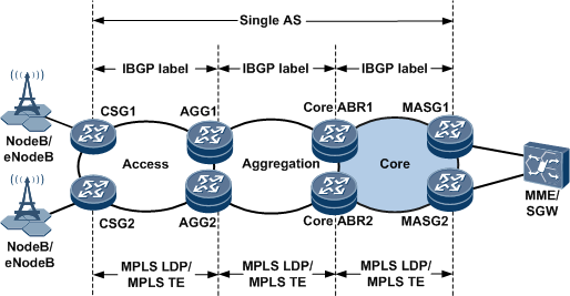
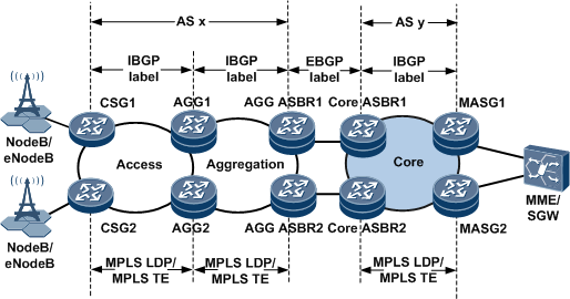
On the network shown in Figure 2, tunnels are deployed as follows:
|
|
Forwarding plane |
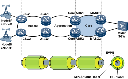
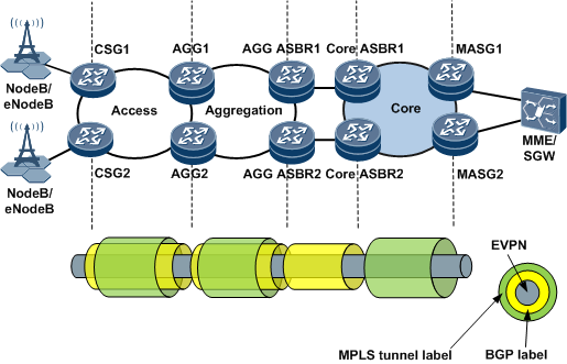
Figure 3 illustrates the forwarding plane of EVPN intra-AS seamless MPLS networking. Seamless MPLS is mainly used to transmit EVPN packets. The following example demonstrates how EVPN packets, including labels and packet content, are transmitted from a CSG to an MASG along the path CSG1->AGG1->core ABR1->MASG1.
|
|
EVPN Inter-AS Seamless MPLS
Network Deployment |
Description |
|
|---|---|---|
Control plane |
Deploying routing protocols |
In Figure 4, routing protocol deployment on devices is as follows:
|
BGP EVPN peer relationship establishment and route advertisement |
On the network shown in Figure 4, BGP EVPN peer relationships need to be established between the following pairs of devices:
The peers exchange MAC/IP routes (Type 2) and IP prefix routes (Type 5) to advertise MAC and IP routing information. |
|
Deploying tunnels |
On the network shown in Figure 5, tunnels are deployed as follows:
|
|
Forwarding plane |
Figure 6 illustrates the forwarding plane of the EVPN inter-AS seamless MPLS networking with a core-layer BGP LSP established. EVPN seamless MPLS is mainly used to transmit EVPN packets. The following example demonstrates how EVPN packets, including VPN labels and packet data, are transmitted from a CSG to an MASG along the path CSG1->AGG1->AGG ASBR1->core ASBR1->MASG1.
Figure 6 Forwarding plane for the EVPN inter-AS seamless MPLS networking with a core-layer BGP LSP established
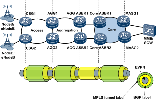 Figure 7 illustrates the forwarding plane for the EVPN inter-AS seamless MPLS networking without a BGP LSP established in the core area. The process of transmitting EVPN packets on this network is similar to that on a network with a BGP LSP established in the core area. The difference is that without a BGP LSP in the core area, the core ASBR removes (rather than swaps) BGP labels from packets and pushes MPLS tunnel labels into these packets. |
|
Reliability
EVPN seamless MPLS network reliability can be improved using a variety of functions. If a network fault occurs, devices with reliability functions enabled immediately detect the fault and switch traffic from the active link to the standby link.
The following examples demonstrate the reliability functions used on an EVPN inter-AS seamless MPLS network.
A fault occurs on a link between a CSG and an AGG.
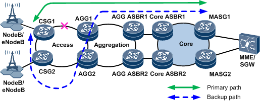
On the EVPN inter-AS seamless MPLS network shown in Figure 8, the active link along the primary path between CSG1 and AGG1 fails. After BFD for LDP LSP or BFD for CR-LSP detects the fault, the BFD module uses LDP FRR, TE hot standby, or BGP FRR to switch traffic from the primary path to the backup path.
A fault occurs on an AGG.
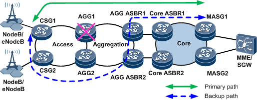
On the EVPN inter-AS seamless MPLS network shown in Figure 9, BGP Auto FRR is configured on CSGs and AGG ASBRs to protect traffic on the BGP LSP between CSG1 and MASG1. If BFD for LDP or BFD for TE detects an AGG1 fault, the BFD module switches traffic from the primary path to the backup path.
A fault occurs on the link between an AGG and an AGG ASBR.
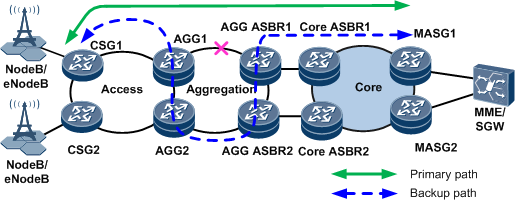
On the EVPN inter-AS seamless MPLS network shown in Figure 10, a fault occurs on the link between AGG1 and AGG ASBR1. After BFD for LDP LSP or BFD for CR-LSP detects the fault, the BFD module instructs LDP FRR, TE hot standby, or BGP FRR to switch traffic from the primary path to the backup path.
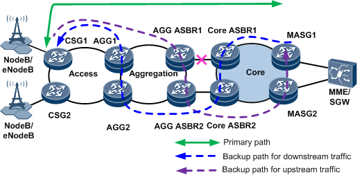
A fault occurs on an AGG ASBR.
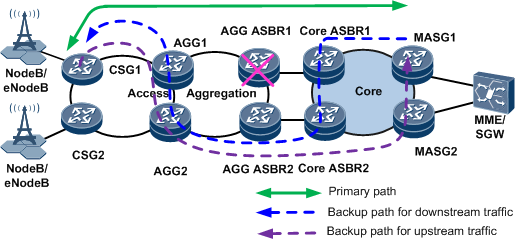
As shown in Figure 11, BFD for LDP or BFD for TE is configured on AGG1, and BFD for interface is configured on core ASBR1. If AGG ASBR1 fails, the BFD modules on AGG1 and core ASBR1 detect the fault and trigger the BGP Auto FRR function. BGP Auto FRR switches both upstream and downstream traffic from the primary path to backup paths.
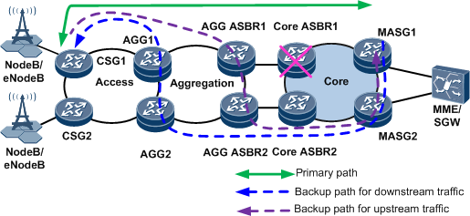
A fault occurs on the link between an AGG ASBR and a core ASBR.
As shown in Figure 12, BFD for interface is configured on AGG ASBR1 and core ASBR1. If the BFD module detects a fault of the link between AGG ASBR1 and core ASBR1, the BFD module triggers the BGP Auto FRR function. BGP Auto FRR switches both upstream and downstream traffic from the primary path to backup paths.
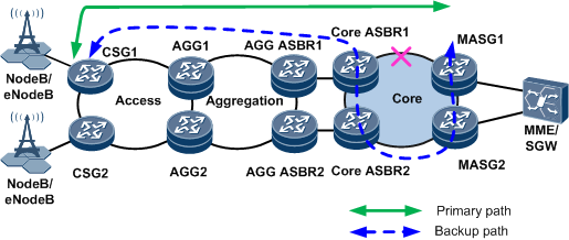
A fault occurs on a core ASBR.
On the EVPN inter-AS seamless MPLS network shown in Figure 13, BFD for interface and BGP Auto FRR are configured on AGG ASBR1. BGP Auto FRR and BFD for LDP (or for TE) are configured on MASGs to protect traffic on the BGP LSP between CSG1 and MASG1. If the BFD module detects a fault on core ASBR1, it switches both upstream and downstream traffic from the primary path to backup paths.
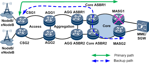
A link fault occurs in the core area.
On the EVPN inter-AS seamless MPLS network shown in Figure 14, BFD for LDP or BFD for TE is configured on core ASBR1. If the BFD module detects a fault on the link between core ASBR1 and MASG1, it instructs the LDP FRR, TE hot standby, or BGP FRR function to switch both upstream and downstream traffic from the primary path to the backup paths.
A fault occurs on an MASG.
As shown in Figure 15, BFD for BGP tunnel is configured on CSG1. BFD for BGP tunnel is implemented in compliance with a standard titled "Bidirectional Forwarding Detection (BFD) for MPLS Label Switched Paths (LSPs)." BFD for BGP tunnel monitors E2E BGP LSPs, including a BGP LSP stitched with an LDP LSP. If MASG1 that functions as a remote PE fails, BFD for BGP LSP can rapidly detect the fault and trigger VPN FRR switching. The BFD module then switches both upstream and downstream traffic from the primary path to the backup path.
A fault occurs on an access-side link.
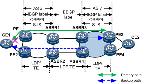
On the inter-AS seamless MPLS network shown in Figure 16, if an E-Trunk in single-active mode detects a link failure, the E-Trunk switches traffic from the primary path to the backup path and PE2's interface connected to CE1 is unblocked. Then upstream traffic on CE1 is switched to PE2. For BUM traffic on the network side, PE1 sends a per-ES A-D route withdraw message to PE2, and PE2 is elected as the DF to forward BUM traffic. After receiving the MAC route advertised by PE2, PE3 switches unicast traffic to PE2.
If an E-Trunk in active-active mode detects a link failure, PE1 sends a per-ES A-D route withdraw message to PE3, and PE3 switches unicast traffic to PE2.
A PE on the access side fails.
If PE1 fails, the original EVPN detection mechanism is triggered, which is similar to that triggered when an access-side link fails. Other PEs switch traffic after detecting PE1's down state rather than receiving a route withdraw request.