EVPN Multi-Homing
Related Concepts
Interface-based and VLAN-based DF election
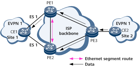
As shown in Figure 1, CE1 is dual-homed to PE1 and PE2. CE2 sends BUM traffic to PE1 and PE2. To prevent CE1 from receiving duplicate traffic from both PE1 and PE2, the EVPN DF election mechanism is introduced to specify either PE1 or PE2 to forward BUM traffic to CE1. If PE1 is elected, it becomes the primary DF, with PE2 functioning as the backup DF. The primary DF forwards BUM traffic from CE2 to CE1.
The PEs establish EVPN BGP peer relationships with each other and then exchange Ethernet segment routes.
Upon receipt of the Ethernet segment routes, each PE generates a multi-homing PE list based on the ESIs carried in the routes. Each multi-homing PE list contains information about all PEs connecting to the same CE.
Each PE then sequences the PEs in each multi-homing PE list based on the source IP addresses carried in Ethernet segment routes. The PEs are numbered in ascending order from 0.
If interface-based DF election is enabled, the PE with the smallest source IP address is elected to be the primary DF. If VLAN-based DF election is enabled, the PE with a specific sequence number is elected to be the primary DF. The sequence number is calculated using the following expression formula: (V mod N) = i, in which i indicates a PE's sequence number, N indicates the number of PEs to which a CE is multi-homed, and V indicates the VLAN ID over an Ethernet segment.

If an Ethernet segment has multiple VLANs bound to, the smallest VLAN ID is used as the value for V.
ESI-based DF priority election
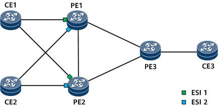
On the network shown in Figure 2, CE1 and CE2 are each dual-homed to PE1 and PE2. The PE interfaces that connect to CE1 have ESI 1 (shown in green), and the PE interfaces that connect to CE2 have ESI 2 (shown in blue). If you want CE3-to-CE1 unicast traffic and CE3-to-CE2 unicast traffic to be transmitted in load-balancing and non-load-balancing modes, respectively, you can set a redundancy mode per ESI instance. Specifically, you can set the redundancy mode of the ESI 1 instance to all-active and that of the ESI 2 instance to single-active.
If you want CE3-to-CE2 BUM traffic to be forwarded by PE1, configure ESI-based DF priority election on PE1 and PE2 and specify PE1 as the primary DF.
AC interface influenced DF election
In CE dual-homing networking, an AC interface's sub-interfaces on the access side are bound to an EVPN instance. If an ESI is set on the interface and one of the sub-interfaces goes down due to a fault or some other reason, the ESI remains valid because the other sub-interfaces bound to the EVPN instance remain up. As a result, the PE does not regenerate ES routes to trigger DF election, which may prevent the BUM traffic from being forwarded.
To resolve this issue, enable the function that the AC interface status influences DF election. This configuration helps check whether the PE has received the auto discovery (AD) routes from all PEs during DF election to determine whether these PEs are qualified for DF election. If a PE has not received the AD routes from a peer PE, the peer PE cannot participate in DF election.
Split horizon
On the network shown in Figure 3, CE1 is dual-homed to PE1 and PE2 and has load balancing enabled. If PE1 and PE2 have established an EVPN BGP peer relationship, after PE1 receives BUM traffic from CE1, it forwards the BUM traffic to PE2. To prevent this problem, EVPN uses split horizon. After PE1 forwards the BUM traffic to PE2, PE2 checks the EVPN ESI label carried in the traffic. If the ESI carried in the label equals the ESI for the link between PE2 and CE1, PE2 does not forward the traffic to CE1, preventing a loop.
Redundancy mode and aliasing
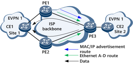
If a CE is multi-homed to several PEs, a redundancy mode can be set to all-active or single-active for PEs connecting to the same CE. The redundancy mode determines whether load balancing is implemented for unicast traffic in CE multi-homing scenarios. If PE1 and PE2 are configured to work in all-active mode, after PE1 and PE2 send Ethernet A-D routes carrying the redundancy mode information to PE3, PE3 sends unicast traffic destined for CE1 to both PE1 and PE2 in load balancing mode.
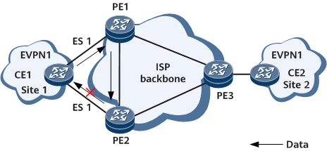
EVPN also supports aliasing. When a CE is multi-homed to several PEs that work in all-active mode, some PEs may fail to learn the MAC addresses on the CE side. Aliasing enables remote PEs to learn the reachability to CE-side MAC addresses based on the ESIs carried in Ethernet A-D routes received from the multi-homing PEs. On the network shown in Figure 4, only PE1 sends MAC/IP advertisement routes carrying CE1-side MAC addresses to PE3. However, PE3 can use Ethernet A-D routes to detect that PE2 can also reach CE1, implementing load balancing.
Rapid convergence
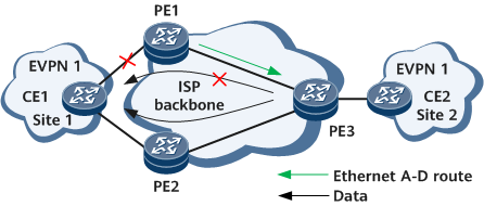
On the network shown in Figure 5, if the link between CE1 and PE1 fails, PE1 advertises an Ethernet A-D route to PE3 to inform that PE1 has become unreachable to site 1. Upon receipt of the route, PE3 withdraws the corresponding route and sends traffic to site 1 only through PE2, implementing rapid route convergence.
Determining the Active/Standby Status of PEs in a Multi-Homing Scenario
On a network where a CE is multi-homed to PEs, the PEs can work in either all-active or single-active redundancy mode. When PEs work in all-active mode, all PEs are in the active state. When PEs work in single-active mode, one PE is in the active state, and the other PEs are in the standby state. Currently, either of the following methods can be used to determine the active/standby status of PEs:
An E-Trunk is used to determine the active/standby status.
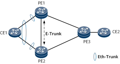
As shown in Figure 6, CE1 is dual-homed to PE1 and PE2 through Eth-Trunk interfaces, and PE1 and PE2 are also connected to CE1 through Eth-Trunk interfaces. An E-Trunk is deployed between PE1 and PE2. In a dual-homing active-active scenario, PE1 and PE2 are both in the active state, according to the E-Trunk configuration. In a dual-homing single-active scenario, PE1 and PE2 to work in active/standby mode, according to the E-Trunk configuration. For details about E-Trunk implementation, see E-Trunk.
DF election determines the active/standby status.
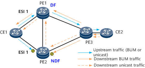
On the network shown in Figure 7, CE1 is dual-homed to PE1 and PE2 through physical interfaces or Eth-Trunk interfaces. The same ESI is configured for the interfaces that connect PE1 and PE2 to CE1. In this case, DF election is performed between PE1 and PE2 (for a detailed process, refer to the foregoing description). Herein, it is assumed that PE1 is elected as the DF, and PE2 is not the DF. In a dual-homing single-active scenario, PE1 (DF) is in the active state, and PE2 (non-DF) is in the standby state. The implementation is as follows:
- For upstream traffic sent by CE1: PE1 properly forwards BUM and unicast traffic, and PE2 blocks such traffic. PE2 blocks the BUM traffic to prevent duplicate traffic. PE2 blocks unicast traffic to specifically prevent CE1 from sending a copy of traffic to each of PE1 and PE2 if CE1 sends unknown unicast traffic (for example, the MAC address has not been learned or ages out). In such a scenario, PE1 functions as a DF and forwards packets properly. However, PE2 may already obtain the destination MAC address of the traffic and considers the traffic as known unicast traffic. If the traffic is not blocked on PE2, both PEs send traffic, leading to duplicate traffic.
- For downstream traffic on PE3: PE1 properly forwards BUM traffic, but PE2 blocks it, according to DF functions. For unicast traffic, PE1 forwards the traffic properly, while PE2 processes the traffic as follows:
- If local and remote FRR for MAC routes is configured between PE1, PE2, and PE3, PE2 forwards the unicast traffic to PE1 and then to CE1.
- If local and remote FRR for MAC routes is not configured between PE1, PE2, and PE3, PE2 blocks the traffic, clears the local MAC route to CE1, and instructs PE3 to withdraw the MAC route with PE2 at the next hop. After the MAC route withdrawal, the unicast traffic sent to PE2 becomes BUM traffic and is forwarded as BUM traffic, preventing packet loss.
Currently, the active/standby status of PEs can be determined through DF election result only in dual-homing single-active scenarios. In dual-homing active-active scenarios, an E-Trunk must be used to allow the two PEs to both work in active status.
Using the DF election result to determine the active/standby status of PEs is supported only when BD EVPN is deployed.