EVPN Interworking Scenarios
Background
Currently, metro networks are evolving towards EVPN. An existing network with a large number of aggregation devices cannot evolve to EVPN in an E2E mode at a time. During the transition, conventional L3VPN, VPWS, or VPLS is used at the aggregation layer, and the core network evolves to EVPN first. In this case, interworking between the EVPN and existing networks is required.
L3VPN Accessing EVPN
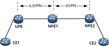
Devices between the UPE and NPE1 reside at the aggregation layer, and devices between NPE1 and NPE2 reside at the core layer. The L3VPN function is deployed at the aggregation layer, and the EVPN function is deployed at the core layer. After accepting access-side user routes, the UPE sends these routes to NPE1 through a BGP VPNv4 peer relationship. Upon receipt of the BGP VPNv4 routes, NPE1 with both an EVPN instance and an L3VPN instance configured imports these routes into the L3VPN instance, re-generates the routes as EVPN routes, and sends the EVPN routes to NPE2 through a BGP EVPN peer relationship. Then, network connectivity can be achieved in the L3VPN accessing EVPN scenario.
VLL Accessing EVPN
In the VLL accessing EVPN networking, a user named CE1 has three sites: CE1-1, CE1-2, and CE1-3; another user named CE2 also has three sites: CE2-1, CE2-2, and CE2-3. NIDs, which aggregate user site, add two VLAN tags to user packets before sending these packets over the aggregation network. In a double-tagged user packet, an S-VLAN ID identifies a NID, and a C-VLAN ID identifies a user site connected to the NID. Users access the VLL network, which is a native Layer 2 network, through the NIDs. An MPLS network is deployed at the aggregation layer between the UPE and NPE1, and uses VLL to carry services. Another MPLS network is deployed at the core layer between NPE1 and NPE2, and uses EVPN to carry services.
VLL accessing EVPN allows different sites of the same user to communicate in the following scenarios:
Single-homing scenario
The access-side main interfaces on NIDs can be used to provide user access. A UPE establishes a PW to each NID. On the NPEs, an EVPN instance is created for each user and the VLL accesses the EVPN instance in PW VE mode. The VLL service is bound to the PW VE main interface, each EVPN instance is bound to a PW VE sub-interface. The sub-interfaces use QinQ encapsulation and forward packets based on S-VLAN and C-VLAN IDs, steering traffic to different EVPN instances.
Figure 2 VLL accessing EVPN (one PW to each NID)
Similarly, the VLL accessing EVPN scenario also allows multiple NIDs to connect to a PW. Multiple NIDs are aggregated onto a switch and then connect to the same PW.
Figure 3 VLL accessing EVPN (multiple NIDs connected to one PW)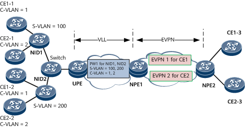
Dual-homing networking
A UPE is dual-homed to the master and backup NPEs through the primary and secondary PWs, respectively, which improves access reliability. EVPN services on the NPEs can be configured to work in single-active or all-active mode. In all-active mode, load balancing can be implemented.
Figure 4 VLL accessing EVPN (dual-homing scenario)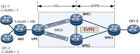
VXLAN Accessing VPLS
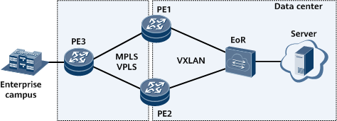
When an enterprise campus network is connected to a data center network, an EVPN VXLAN network needs to be deployed in the data center, and the data center network is connected to the enterprise campus network through an MPLS L2VPN. In this case, the functions of terminating VXLAN packets and accessing VPLS need to be deployed.
In Figure 5, the EOR switch, functioning as a data center gateway, connects to the backbone network through egress PE1 and PE2 of the data center network. PE3, the egress of the enterprise campus network, is connected to PE1 and PE2 through the MPLS VPLS network. PE1 and PE2 are configured to terminate VXLAN packets and access the MPLS VPLS network to connect the data center to the campus network.
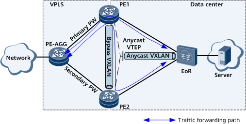
Interworking Primary and Secondary PWs with an Anycast VXLAN Tunnel in an EVPN Active-Active Scenario
In Figure 6, PE1 and PE2 are egresses of the data center network. PE1 and PE2 work in active-active mode with a bypass VXLAN tunnel deployed between them. They use an anycast VTEP address to establish a VXLAN tunnel with the EOR switch. In this case, PE1, PE2, and the EOR switch can communicate with each other. PE1 and PE2 communicate with the external network (an access network or the Internet) through the VPLS network. VPLS PW redundancy is deployed on the VPLS network. That is, the PE-AGG connects to PE1 and PE2 through primary and secondary PWs, respectively. In this example, the PW between the PE-AGG and PE1 is the primary PW.
Through the EOR, the server in the data center can send traffic to PE1 and PE2. Traffic received by PE1 is sent directly to the PE-AGG through the primary PW. Traffic received by PE2 is forwarded to PE1 through the bypass VXLAN tunnel and also sent to the PE-AGG through the primary PW. Traffic from the PE-AGG to the server is transmitted along the reverse paths of the preceding forward paths.
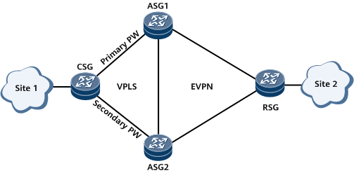
Interworking VPLS with MPLS EVPN
VPLS technology has some inherent defects. For example, it does not support load balancing and consumes a large number of network resources (because MAC learning and ARP learning involve broadcasting on the entire network). With the application of EVPN on the live network, the VPLS network will gradually evolve to the EVPN network. However, a user network environment is complex and may not completely evolve to the EVPN network. VPLS is deployed on some devices, and EVPN is deployed on the other devices. In this case, you can configure interworking between VPLS and MPLS EVPN to implement connectivity of the entire network.
ASG1 sends an Ethernet Auto-Discovery route to the RSG as the PW interface is assigned an ESI and the PW is up on ASG1.
After the CSG forwards a Layer 2 packet sent by site 1 to ASG1, ASG1 generates a MAC route based on the MAC address carried in the Layer 2 packet and sends the route to the RSG through a BGP EVPN peer relationship. The RSG uses the MAC route and Ethernet Auto-Discovery route to generate a MAC forwarding entry. Similarly, the RSG sends a MAC route carrying site 2's MAC address to ASG1, and ASG1 generate a MAC forwarding entry.
After the forwarding entries are created, they can be used to guide unicast and BUM traffic forwarding. The process of forwarding unicast traffic from site 1 to site 2 is used as an example. After traffic is sent to ASG1 through the primary PW, ASG1 finds a next-hop MAC address based on a MAC route sent by the RSG and forwards the traffic to the RSG. The RSG then forwards the traffic to site 2.

Although ASG1 and ASG2 exchange Ethernet segment routes, DF election between ASG1 and ASG2 is determined by the PW status, not by the Ethernet segment routes. ASG1 connected to the primary PW is the primary DF, and ASG2 connected to the secondary PW is the secondary DF.
In BUM traffic forwarding scenarios, the network provides the split horizon function, and the backup DF blocks traffic. Therefore, no traffic loop or excess packets occur on the network.
Interworking VPLS with an SRv6 EVPN
Currently, EVPN and SRv6 tunneling technologies are becoming increasingly mature. Conventional VPLS over MPLS is gradually evolving to EVPN over SRv6. However, a large number of conventional VPLS services exist on the live network, and these services cannot all evolve to EVPN services at a time. As a result, VPLS over MPLS may be deployed on some networks, and EVPN over SRv6 may be deployed on the other networks. In this case, you need to deploy the function of interworking VPLS with SRv6 EVPN to implement network connectivity.
In Figure 8, VPLS over MPLS is deployed between the UPE and SPEs. The UPE establishes the primary and secondary PWs to SPE1 and SPE2, respectively, through negotiation. EVPN over SRv6 is deployed between the NPE and SPEs. SPE1 and SPE2 establish BGP EVPN peer relationships with the NPE. BDs are configured and bound to VSIs and EVPN instances on SPE1 and SPE2 so that both PWs in the VSIs access the EVPN instance through BDs. DF election between SPE1 and SPE2 is associated with the primary/secondary PW status. SPE1 connected to the primary PW is the primary DF, and SPE2 connected to the secondary PW is the secondary DF. The same ESI is set for the primary and secondary PW interfaces that connect SPE1 and SPE2 to the UPE, respectively. The process of advertising MAC routes and forwarding traffic is as follows:
If the PW interface is assigned an ESI and the PW is up on SPE1, SPE1 sends an Ethernet A-D route to the NPE.
After the UPE forwards a Layer 2 packet sent by site 1 to SPE1, SPE1 generates a MAC route based on the MAC address carried in the Layer 2 packet and sends the route to the NPE through a BGP EVPN peer relationship. The NPE uses the MAC route and Ethernet A-D route to generate a MAC forwarding entry. Similarly, the NPE also sends a MAC route carrying site 2's MAC address to the SPE, and the SPE generates a MAC forwarding entry.
After the forwarding entries are created, they can be used to guide unicast and BUM traffic forwarding. The process of forwarding unicast traffic from site 1 to site 2 is used as an example. After traffic is sent to SPE1 over the primary PW, SPE1 finds a next-hop MAC address based on the MAC route sent by the NPE and forwards the traffic to the NPE. The NPE then forwards the traffic to site 2.
