EVPN E-Tree
Background
As the number of services carried on an EVPN increases, the number of user MAC addresses managed by the EVPN is also increasing. The user MAC addresses are flooded on the network through EVPN routes. As a result, all interfaces in the same broadcast domain can communicate with each other at Layer 2. However, broadcast, unknown unicast, multicast (BUM), and unicast traffic cannot be isolated for users who do not need to communicate with each other. To isolate interfaces that do not need to communicate with each other in the same broadcast domain, you can deploy the EVPN E-Tree function on the network.
Fundamentals
A leaf AC interface and a root AC interface can send traffic to each other. However, flows between leaf AC interfaces are isolated from each other.
A root AC interface can communicate with the other root AC interfaces and with leaf AC interfaces.
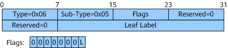
To implement the preceding functions, an E-Tree extended community attribute is defined in a standard protocol. Figure 1 shows the format of a packet with the E-Tree extended community attribute. The packet includes the Leaf Label field and the Flags field. The Flags field contains 8 bits, in which the first 7 bits are all zeros and the last identifies whether an EVPN MAC route is from a leaf AC interface. Value 1 indicates that the MAC route comes from this interface. The extended community attribute can be advertised through Ethernet A-D per-ES routes and MAC routes on an EVPN, so that known unicast traffic and BUM traffic on leaf AC interfaces are isolated from each other.
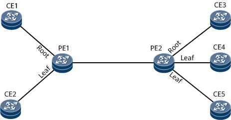
PE1 and PE2 transmit AC-side MAC addresses to each other through MAC routes. Take the MAC address (MAC1) of the AC interface on CE2 as an example. Because the AC interface has the leaf attribute, a MAC route carrying the MAC1 address also carries the extended community attribute of EVPN E-Tree. All bits in the Leaf Label field of the attribute are set to 0, and the L bit in the Flags field is set to 1. PE1 then sends this MAC route to PE2.
Upon receipt, PE2 checks the L bit in the Flags field. Because this bit is set to 1, PE2 marks the entry corresponding to MAC1 in the local MAC table.
When PE2 receives traffic destined for CE2 from its own leaf AC interface, PE2 determines that the traffic needs to be sent to the remote leaf AC interface based on the flag in the local MAC routing table and discards the traffic. In this way, known unicast traffic is isolated between leaf AC interfaces.
After EVPN E-Tree is configured on the network, PE1 and PE2 send a special Ethernet A-D per ES route to each other. After EVPN E-Tree is configured on the network, PE1 and PE2 send a special Ethernet A-D per ES route to each other. A regular Ethernet A-D per-ES route carries the ESI attribute. However, the ESI field in the Ethernet A-D per-ES route used by EVPN E-Tree is set to all zeros, and the route carries the extended community attribute of EVPN E-Tree. The Leaf Label field of this attribute uses a label value, and the L bit in the Flags field is set to 0.
After PE1 receives the Ethernet A-D per ES route, it determines that the route is used to transmit the leaf label because the ESI field value is all zeros. PE1 then saves the label.
When PE1 needs to send BUM traffic from its leaf AC interface to PE2, PE1 encapsulates the saved leaf label into the BUM packets and then sends them to PE2.
Upon receipt, PE2 finds the locally allocated leaf label in the BUM packets. Therefore, PE2 does not send the traffic to CE4 or CE5. Instead, PE2 sends the traffic only to CE3, implementing BUM traffic isolation between leaf AC interfaces.

EVPN E-Tree supports the following types of AC interfaces: main interfaces bound to common EVPN instances, EVC Layer 2 sub-interfaces associated with BDs, and VLAN sub-interfaces.
In a CE dual-homing scenario, ensure that the same root or leaf attribute is set for the same VLAN sub-interface in the same broadcast domain on two PEs. If the leaf attribute is set on both PEs, the Leaf label can replace the ESI label to implement split horizon.
Different root or leaf attributes can be set for a PE's interfaces or sub-interfaces that connect to different CEs.
Determining the Active/Standby Status of PEs in a Multi-Homing Scenario
On a network where a CE is multi-homed to PEs, the PEs can work in either all-active or single-active redundancy mode. When PEs work in all-active mode, all PEs are in the active state. When PEs work in single-active mode, one PE is in the active state, and the other PEs are in the standby state. Currently, the following methods can be used to determine the active/standby status of PEs:
An E-Trunk is used to determine the active/standby status.
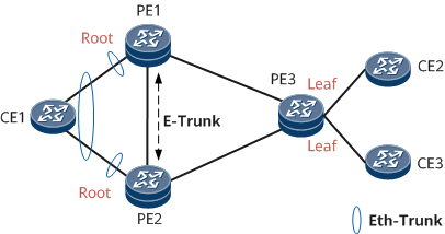
As shown in Figure 6, CE1 is dual-homed to PE1 and PE2 through Eth-Trunk interfaces, and PE1 and PE2 are also connected to CE1 through Eth-Trunk interfaces. An E-Trunk is deployed between PE1 and PE2. In a dual-homing active-active scenario, PE1 and PE2 are both in the active state, according to the E-Trunk configuration. In a dual-homing single-active scenario, PE1 and PE2 to work in active/standby mode, according to the E-Trunk configuration. For details about E-Trunk implementation, see E-Trunk.
DF election determines the active/standby status.
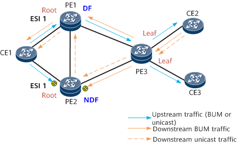
On the network shown in Figure 7, CE1 is dual-homed to PE1 and PE2 through physical interfaces or Eth-Trunk interfaces. The same ESI is configured for the interfaces that connect PE1 and PE2 to CE1. PE1 and PE2 are elected as DFs. In this example, PE1 is elected as the DF, and PE2 is a non-DF. For details about DF election, see EVPN Multi-Homing. In a dual-homing single-active scenario, PE1 (DF) is in the active state, and PE2 (non-DF) is in the standby state. The implementation is as follows:
- For upstream traffic sent by CE1: PE1 properly forwards BUM and unicast traffic, and PE2 blocks such traffic. PE2 blocks the BUM traffic to prevent duplicate traffic. PE2 blocks unicast traffic to specifically prevent CE1 from sending to a copy of traffic to each of PE1 and PE2 if CE1 sends unknown unicast traffic (for example, the MAC address has not been learned or ages out). In such a scenario, PE1 functions as a DF and forwards packets properly. However, PE2 may already obtain the destination MAC address of the traffic and considers the traffic as known unicast traffic. If the traffic is not blocked on PE2, both PEs send traffic, leading to duplicate traffic.
- For downstream traffic on PE3: PE1 properly forwards BUM traffic, but PE2 blocks it, according to DF functions. For unicast traffic, PE1 forwards the traffic properly, while PE2 processes the traffic as follows:
- If local and remote FRR for MAC routes is configured between PE1, PE2, and PE3, PE2 forwards the unicast traffic to PE1 and then to CE1.
- If local and remote FRR for MAC routes is not configured between PE1, PE2, and PE3, PE2 blocks the traffic, clears the local MAC route to CE1, and instructs PE3 to withdraw the MAC route with PE2 at the next hop. After the MAC route withdrawal, the unicast traffic sent to PE2 becomes BUM traffic and is forwarded as BUM traffic, preventing packet loss.
Currently, the active/standby status of PEs can be determined through DF election result only in dual-homing single-active scenarios. In dual-homing active-active scenarios, an E-Trunk must be used to allow the two PEs to both work in active status.
Using the DF election result to determine the active/standby status of PEs is supported only when BD EVPN is deployed.
Application Scenarios
Currently, EVPN E-Tree can be used in two scenarios: EVPN E-Tree over MPLS and EVPN E-Tree over SRv6. The differences between the two modes are as follows:
Application Scenarios |
Public Network Tunnel |
BUM Traffic Forwarding |
|---|---|---|
EVPN E-Tree over MPLS |
MPLS LDP/MPLS TE |
When a PE sends BUM traffic from a leaf interface to the peer PE, the PE encapsulates the leaf label value in the traffic. After receiving BUM traffic, the peer PE finds the leaf label allocated by itself and does not forward the traffic to the interface with the leaf attribute. |
EVPN E-Tree over SRv6 |
SRv6 BE/SRv6 TE Policy |
When a PE sends BUM traffic from a leaf interface to the peer PE, the PE encapsulates the Arguments value (a field in a prefix SID) sent by the peer PE into the traffic. After receiving BUM traffic, the remote PE parses the valid Arguments value and does not forward the traffic to the interface with the Leaf attribute. |