Example for Configuring IS-IS Load Balancing
This section describes how to configure IS-IS load balancing.
Networking Requirements
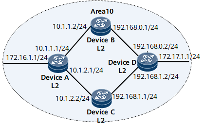
In Figure 1:
Device A, Device B, Device C, and Device D run IS-IS for IP interworking.
Device A, Device B, Device C, and Device D are Level-2 devices in Area 10.
It is required that traffic from Device A to Device D be load-balanced between Device B and Device C.
Device Name |
Interface |
IP Address |
|---|---|---|
Device A |
GE0/1/16 |
172.16.1.1/24 |
GE0/1/0 |
10.1.1.1/24 |
|
GE0/1/8 |
10.1.2.1/24 |
|
Device B |
GE0/1/0 |
10.1.1.2/24 |
GE0/1/8 |
192.168.0.1/24 |
|
Device C |
GE0/1/0 |
10.1.2.2/24 |
GE0/1/8 |
192.168.1.1/24 |
|
Device D |
GE0/1/16 |
172.17.1.1/24 |
GE0/1/0 |
192.168.0.2/24 |
|
GE0/1/8 |
192.168.1.2/24 |
Configuration Roadmap
The configuration roadmap is as follows:
Configure basic IS-IS functions on each router for IP interworking.
Cancel load balancing and view the routing table.
Configure load balancing on Device A and view the routing table.
Configure load balancing on Device A.
(Optional) Configure the priority for equal-cost routes on Device A.
Data Preparation
To complete the configuration, you need the following data:
Area addresses and levels of the four routers
Number (1 in this example) of equal-cost routes for load balancing on Device A
Load balancing mode on Device A
Priority (1 in this example) of equal-cost routes on Device C
Procedure
- Configure an IP address for each interface. For configuration details, see Configuration Files in this section.
- Configure basic IS-IS functions. For configuration details, see Configuration Files in this section.
- Set the maximum number of equal-cost routes for load balancing to 1 on Device A to cancel load balancing.
[~DeviceA] isis 1
[~DeviceA-isis-1] maximum load-balancing 1
[*DeviceA-isis-1] commit
[~DeviceA-isis-1] quit
# Display the routing table of Device A.
[~DeviceA] display isis route
                         Route information for ISIS(1)
                         -----------------------------
                        ISIS(1) Level-2 Forwarding Table
                        --------------------------------
 IPV4 Destination    IntCost   ExtCost ExitInterface   NextHop          Flags
---------------------------------------------------------------------------
 192.168.1.0/24      20        NULL    GE0/1/8         10.1.2.2         A/-/-/-/-
 10.1.1.0/24         10        NULL    GE0/1/0         Direct           D/-/L/-/-
 172.16.1.0/24       10        NULL    GE0/1/16         Direct           D/-/L/-/-
 172.17.1.0/24     30      NULL    GE0/1/0        10.1.1.2         A/-/-/-/-
 10.1.2.0/24         10        NULL    GE0/1/8         Direct           D/-/L/-/-
 192.168.0.0/24      20        NULL    GE0/1/0         10.1.1.2         A/-/-/-/-
     Flags: D-Direct, A-Added to URT, L-Advertised in LSPs, S-IGP Shortcut,
                               U-Up/Down Bit Set
     Protect Type: L-Link Protect, N-Node Protect
As shown in the routing table, when the maximum number of equal-cost routes for load balancing is set to 1, the next hop of the route to 172.17.1.0 is 10.1.1.2 because the system ID of Device B is smaller, and IS-IS chooses the route with next hop 10.1.1.2 as the unique optimal route.
- Restore the number of equal-cost routes for load balancing on Device A to the default value.
[~DeviceA] isis 1
[~DeviceA-isis-1] undo maximum load-balancing
[*DeviceA-isis-1] commit
[~DeviceA-isis-1] quit
# View the routing table of Device A.
[~DeviceA] display isis route
                         Route information for ISIS(1)
                         -----------------------------
                        ISIS(1) Level-2 Forwarding Table
                        --------------------------------
 IPV4 Destination    IntCost   ExtCost ExitInterface   NextHop          Flags
---------------------------------------------------------------------------
 192.168.1.0/24      20        NULL    GE0/1/8         10.1.2.2         A/-/-/-/-
 10.1.1.0/24         10        NULL    GE0/1/0         Direct           D/-/L/-/-
 172.16.1.0/24       10        NULL    GE0/1/16         Direct           D/-/L/-/-
 172.17.1.0/24     30       NULL     GE0/1/0       10.1.1.2         A/-/-/-/-
                                       GE0/1/8       10.1.2.2
 10.1.2.0/24         10        NULL    GE0/1/8         Direct           D/-/L/-/-
 192.168.0.0/24      20        NULL    GE0/1/0         10.1.1.2         A/-/-/-/-
     Flags: D-Direct, A-Added to URT, L-Advertised in LSPs, S-IGP Shortcut,
                                 U-Up/Down Bit Set
     Protect Type: L-Link Protect, N-Node Protect
As shown in the routing table, after the default configuration of load balancing is restored, the route with the next hop of 10.1.1.2 (DeviceB) and the route with the next hop of 10.1.2.2 (DeviceC) on routerDeviceA become valid because the maximum number of equal-cost routes is 64.
Configuration Files
Device A configuration file
#
sysname DeviceA
#
isis 1
 is-level level-2
 network-entity 10.0000.0000.0001.00
#
interface GigabitEthernet0/1/0
 undo shutdown
 ip address 10.1.1.1 255.255.255.0
 isis enable 1
#
interface GigabitEthernet0/1/8
 undo shutdown
 ip address 10.1.2.1 255.255.255.0
 isis enable 1
#
interface GigabitEthernet0/1/16
 undo shutdown
 ip address 172.16.1.1 255.255.255.0
 isis enable 1
#
return
Device B configuration file
#
sysname DeviceB
#
isis 1
 is-level level-2
 network-entity 10.0000.0000.0002.00
#
interface GigabitEthernet0/1/0
 undo shutdown
 ip address 10.1.1.2 255.255.255.0
 isis enable 1
#
interface GigabitEthernet0/1/8
 undo shutdown
 ip address 192.168.0.1 255.255.255.0
 isis enable 1
#
return
Device C configuration file
#
sysname DeviceC
#
isis 1
 is-level level-2
 network-entity 10.0000.0000.0003.00
#
interface GigabitEthernet0/1/0
 undo shutdown
 ip address 10.1.2.2 255.255.255.0
 isis enable 1
#
interface GigabitEthernet0/1/8
 undo shutdown
 ip address 192.168.1.1 255.255.255.0
 isis enable 1
#
return
Device D configuration file
#
sysname DeviceD
#
isis 1
 is-level level-2
 network-entity 10.0000.0000.0004.00
#
interface GigabitEthernet0/1/0
 undo shutdown
 ip address 192.168.0.2 255.255.255.0
 isis enable 1
#
interface GigabitEthernet0/1/8
 undo shutdown
 ip address 192.168.1.2 255.255.255.0
 isis enable 1
#
interface GigabitEthernet0/1/16
 undo shutdown
 ip address 172.17.1.1 255.255.255.0
 isis enable 1
#
return