Example for Configuring Local MT
This section provides an example showing how to configure local MT on IS-IS networks so that multicast packets can be transmitted on a TE tunnel.
Networking Requirements
When multicast and an Interior Gateway Protocol (IGP) Shortcut-enabled Multiprotocol Label Switching (MPLS) traffic engineering (TE) tunnel are configured on a network, the outbound interface of the route calculated by IS-IS may not be a physical interface but a TE tunnel interface. Multicast Join packets are transparent to routers through which the TE tunnel passes. Therefore, these devices cannot generate multicast forwarding entries. As a result, these devices discard received multicast packets from the multicast source.
After local MT is enabled, if the outbound interface of a calculated route is an IGP Shortcut-enabled TE tunnel interface, the routing management (RM) module creates an independent Multicast IGP (MIGP) routing table for the multicast protocol, calculates a physical outbound interface for the route, and adds the route to the MIGP routing table. Local MT resolves the conflict between multicast and a TE tunnel.
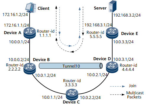
Figure 1 shows IS-IS local MT networking.
DeviceA, DeviceB, DeviceC, DeviceD, and DeviceE run IS-IS, and they are Level-2 devices.
A TE tunnel is established between DeviceB and DeviceD.
IGP Shortcut is enabled on DeviceB.
Device Name |
Interface |
IP Address |
|---|---|---|
DeviceA |
GE0/1/0 |
172.16.1.1/24 |
GE0/1/8 |
10.0.0.1/24 |
|
DeviceB |
GE0/1/0 |
10.0.0.2/24 |
GE0/1/8 |
10.0.1.2/24 |
|
DeviceC |
GE0/1/0 |
10.0.1.1/24 |
GE0/1/8 |
10.0.2.2/24 |
|
DeviceD |
GE0/1/0 |
10.0.3.1/24 |
GE0/1/8 |
10.0.2.1/24 |
|
DeviceE |
GE0/1/0 |
10.0.3.3/24 |
GE0/1/8 |
192.168.3.1/24 |
Configuration Roadmap
The configuration roadmap is as follows:
Enable basic IS-IS functions on each router.
Configure the Protocol Independent Multicast Sparse Mode (PIM-SM).
Configure an MPLS Resource Reservation Protocol (RSVP) TE tunnel and enable IGP Shortcut.
Enable local MT.
Data Preparation
To complete the configuration, you need the following data:
IP address of each router interface, as shown in Figure 1, area address 10, and originating system ID starting from 0000.0000.0001. routers are Level-2 devices.
Tunnel interface TE Tunnel 10, IP address of Loopback 0, tunnel encapsulation protocol MPLS TE, destination address 4.4.4.4, and tunnel ID 100
Procedure
- Assign an IP address for each interface and enable IS-IS.
In Figure 1, assign an IP address and the mask for each interface and enable IS-IS. For configuration details, see Configuration Files in this section.
- Configure PIM-SM.
# Enable multicast on all routers and enable PIM-SM on all interfaces except GE 0/1/0 on DeviceA. The configurations on DeviceB, DeviceC, DeviceD, and DeviceE are similar to those on DeviceA. For configuration details, see Configuration Files in this section.
[~DeviceA] multicast routing-enable
[*DeviceA] interface gigabitethernet 0/1/8
[*DeviceA-GigabitEthernet0/1/8] pim sm
[*DeviceA-GigabitEthernet0/1/8] commit
[~DeviceA-GigabitEthernet0/1/8] quit
# Enable IGMP on the interface through which DeviceA is connected to hosts.
[~DeviceA] interface gigabitethernet 0/1/0
[~DeviceA-GigabitEthernet0/1/0] igmp enable
[*DeviceA-GigabitEthernet0/1/0] igmp version 3
[*DeviceA-GigabitEthernet0/1/0] commit
# Configure a C-BSR and a C-RP. Set the service range of the RP on DeviceD and specify the locations of the C-BSR and the C-RP.
[~DeviceD] pim
[*DeviceD-pim] c-bsr gigabitethernet 0/1/0
[*DeviceD-pim] c-rp gigabitethernet 0/1/0
[*DeviceD-pim] commit
# Run the display multicast routing-table command to view the multicast routing table of a router. The multicast routing table on DeviceC is as follows:
[~DeviceC] display multicast routing-table
Multicast routing table of VPN-Instance: public net
 Total 1 entry
 00001. (192.168.3.2, 224.31.31.31)
       Uptime: 15:03:04
       Upstream Interface: GigabitEthernet0/1/8
       List of 1 downstream interface
           1:  GigabitEthernet0/1/0
- Configure an MPLS RSVP-TE tunnel.
# Configure DeviceB.
[~DeviceB] mpls lsr-id 2.2.2.2
[*DeviceB] mpls
[*DeviceB-mpls] mpls te
[*DeviceB-mpls] mpls rsvp-te
[*DeviceB-mpls] mpls te cspf
[*DeviceB-mpls] quit
[*DeviceB] interface gigabitethernet 0/1/8
[*DeviceB-GigabitEthernet0/1/8] mpls
[*DeviceB-GigabitEthernet0/1/8] mpls te
[*DeviceB-GigabitEthernet0/1/8] mpls rsvp-te
[*DeviceB-GigabitEthernet0/1/8] quit
[*DeviceB] isis 1
[*DeviceB-isis-1] cost-style wide
[*DeviceB-isis-1] traffic-eng level-2
[*DeviceB-isis-1] commit
[~DeviceB-isis-1] quit
# Configure DeviceC.
[~DeviceC] mpls lsr-id 3.3.3.3
[*DeviceC] mpls
[*DeviceC-mpls] mpls te
[*DeviceC-mpls] mpls rsvp-te
[*DeviceC-mpls] mpls te cspf
[*DeviceC-mpls] quit
[*DeviceC] interface gigabitethernet 0/1/0
[*DeviceC-GigabitEthernet0/1/0] mpls
[*DeviceC-GigabitEthernet0/1/0] mpls te
[*DeviceC-GigabitEthernet0/1/0] mpls rsvp-te
[*DeviceC-GigabitEthernet0/1/0] quit
[*DeviceC] interface gigabitethernet 0/1/8
[*DeviceC-GigabitEthernet0/1/8] mpls
[*DeviceC-GigabitEthernet0/1/8] mpls te
[*DeviceC-GigabitEthernet0/1/8] mpls rsvp-te
[*DeviceC-GigabitEthernet0/1/8] quit
[*DeviceC] isis 1
[*DeviceC-isis-1] cost-style wide
[*DeviceC-isis-1] traffic-eng level-2
[*DeviceC-isis-1] commit
[~DeviceC-isis-1] quit
# Configure DeviceD.
[~DeviceD] mpls lsr-id 4.4.4.4
[*DeviceD] mpls
[*DeviceD-mpls] mpls te
[*DeviceD-mpls] mpls rsvp-te
[*DeviceD-mpls] mpls te cspf
[*DeviceD-mpls] quit
[*DeviceD] interface gigabitethernet 0/1/0
[*DeviceD-GigabitEthernet0/1/0] mpls
[*DeviceD-GigabitEthernet0/1/0] mpls te
[*DeviceD-GigabitEthernet0/1/0] mpls rsvp-te
[*DeviceD-GigabitEthernet0/1/0] quit
[*DeviceD] isis 1
[*DeviceD-isis-1] cost-style wide
[*DeviceD-isis-1] traffic-eng level-2
[*DeviceD-isis-1] commit
[~DeviceD-isis-1] quit
# Configure an MPLS TE tunnel and enable IGP Shortcut.
Configure an MPLS TE tunnel on DeviceB and enable IGP Shortcut.
[~DeviceB] interface Tunnel 10
[~DeviceB-Tunnel10] ip address unnumbered interface loopback 0
[*DeviceB-Tunnel10] tunnel-protocol mpls te
[*DeviceB-Tunnel10] destination 4.4.4.4
[*DeviceB-Tunnel10] mpls te tunnel-id 100
[*DeviceB-Tunnel10] mpls te igp shortcut isis
[*DeviceB-Tunnel10] mpls te igp metric relative -10
[*DeviceB-Tunnel10] isis enable 1
[*DeviceB-Tunnel10] commit
[~DeviceB-Tunnel10] quit
# Display the routing table on DeviceB. You can find that IGP Shortcut is enabled.
[~DeviceB] display isis route
                         Route information for ISIS(1)
                         -----------------------------
                        ISIS(1) Level-2 Forwarding Table
                        --------------------------------
 IPV4 Destination     IntCost    ExtCost ExitInterface   NextHop          Flags
--------------------------------------------------------------------------------
 3.3.3.3/32           10         NULL    GE0/1/8         10.0.1.1       A/-/-/-
 172.16.1.0/24        20         NULL    GE0/1/0         10.0.0.1       A/-/-/-
 2.2.2.2/32           0          NULL    Loop0           Direct         D/-/L/-
 192.168.3.0/24       25         NULL    Tun0/1/0        2.2.2.2        A/S/-/-
 5.5.5.5/32           15         NULL    Tun0/1/0        2.2.2.2        A/S/-/-
 10.0.0.0/24          10         NULL    GE0/1/0         Direct         D/-/L/-
 10.0.1.0/24          10         NULL    GE0/1/8         Direct         D/-/L/-
 4.4.4.4/32           5          NULL    Tun0/1/0        2.2.2.2        A/S/-/-
 10.0.2.0/24          15         NULL    Tun0/1/0        2.2.2.2        A/S/-/-
 10.0.3.0/24          15         NULL    Tun0/1/0        2.2.2.2        A/S/-/-
     Flags: D-Direct, A-Added to URT, L-Advertised in LSPs, S-IGP Shortcut,
                               U-Up/Down Bit Set
     Protect Type: L-Link Protect, N-Node Protect
# Display the multicast routing table on DeviceC through which the TE tunnel passes.
[~DeviceC] display multicast routing-table
No multicast routing entry is displayed, indicating that multicast packets have been discarded.
- Configure local MT.
# Enable local MT on DeviceB.
[~DeviceB] isis
[~DeviceB-isis-1] local-mt enable
[*DeviceB-isis-1] commit
- Verify the configuration.
# Display the multicast routing table on DeviceC again. The command output shows that multicast routes are displayed.
[~DeviceC] display multicast routing-table
Multicast routing table of VPN-Instance: public net
 Total 1 entry
 00001. (192.168.3.2, 224.31.31.31)
       Uptime: 00:00:19
       Upstream Interface: GigabitEthernet0/1/8
       List of 1 downstream interface
           1:  GigabitEthernet0/1/0
# Display the MIGP routing table on DeviceB.
[~DeviceB] display migp routing-table
Route Flags: R - relay, D - download to fib, T - to vpn-instance, B - black hole route
------------------------------------------------------------------------------
Routing Table: MIGP
         Destinations : 5        Routes : 5
Destination/Mask    Proto  Pre  Cost     Flags NextHop         Interface
      4.4.4.4/32    ISIS   15   20             10.0.1.1        GE0/1/8
      5.5.5.5/32    ISIS   15   30             10.0.1.1        GE0/1/8
     10.0.2.0/24    ISIS   15   20             10.0.1.1        GE0/1/8
     10.0.3.0/24    ISIS   15   30             10.0.1.1        GE0/1/8
  192.168.3.0/24    ISIS   15   40             10.0.1.1        GE0/1/8
The MIGP routing table shows that the original outbound interface (TE tunnel interface) has been replaced with a physical interface.
Configuration Files
DeviceA configuration file
#
 sysname DeviceA
#
 router id 1.1.1.1
#
 multicast routing-enable
#
isis 1
 is-level level-2
 cost-style wide
 network-entity 10.0000.0000.0001.00
#
interface GigabitEthernet0/1/8
 ip address 10.0.0.1 255.255.255.0
 isis enable 1
 pim sm
#
interface GigabitEthernet0/1/0
 ip address 172.16.1.1 255.255.255.0
 isis enable 1
 igmp enable
#
interface LoopBack0
 ip address 1.1.1.1 255.255.255.255
#
return
DeviceB configuration file
#
 sysname DeviceB
#
 router id 2.2.2.2
#
 multicast routing-enable
#
 mpls lsr-id 2.2.2.2
 mpls
  mpls te
  mpls rsvp-te
  mpls te cspf
#
isis 1
 is-level level-2
 cost-style wide
 network-entity 10.0000.0000.0002.00
 traffic-eng level-2
 local-mt enable
#
interface GigabitEthernet0/1/0
 ip address 10.0.0.2 255.255.255.0
 isis enable 1
 pim sm
#
interface GigabitEthernet0/1/8
 ip address 10.0.1.2 255.255.255.0
 isis enable 1
 pim sm
 mpls
 mpls te
 mpls rsvp-te
#
interface LoopBack0
 ip address 2.2.2.2 255.255.255.255
 isis enable 1
 pim sm
#
interface Tunnel10
 ip address unnumbered interface LoopBack0
 tunnel-protocol mpls te
 destination 4.4.4.4
 mpls te tunnel-id 100
 mpls te igp shortcut isis
 mpls te igp metric relative -10
 isis enable 1
 pim sm
#
pim
 C-BSR LoopBack0
 C-RP LoopBack0
#
return
DeviceC configuration file
#
 sysname DeviceC
#
 router id 3.3.3.3
#
 multicast routing-enable
#
 mpls lsr-id 3.3.3.3
 mpls
  mpls te
  mpls rsvp-te
  mpls te cspf
#
isis 1
 is-level level-2
 cost-style wide
 network-entity 10.0000.0000.0003.00
 traffic-eng level-2
#
interface GigabitEthernet0/1/0
 ip address 10.0.1.1 255.255.255.0
 isis enable 1
 pim sm
 mpls
 mpls te
 mpls rsvp-te
#
interface GigabitEthernet0/1/8
 ip address 10.0.2.2 255.255.255.0
 isis enable 1
 pim sm
 mpls
 mpls te
 mpls rsvp-te
#
interface LoopBack0
 ip address 3.3.3.3 255.255.255.255
 isis enable 1
#
return
DeviceD configuration file
#
 sysname DeviceD
#
 router id 4.4.4.4
#
 multicast routing-enable
#
 mpls lsr-id 4.4.4.4
 mpls
  mpls te
  mpls rsvp-te
  mpls te cspf
#
isis 1
 is-level level-2
 cost-style wide
 network-entity 10.0000.0000.0004.00
 traffic-eng level-2
#
interface GigabitEthernet0/1/0
 ip address 10.0.3.1 255.255.255.0
 isis enable 1
 pim sm
#
interface GigabitEthernet0/1/8
 ip address 10.0.2.1 255.255.255.0
 isis enable 1
 pim sm
 mpls
 mpls te
 mpls rsvp-te
#
interface LoopBack0
 ip address 4.4.4.4 255.255.255.255
 isis enable 1
 pim sm
#
return
DeviceE configuration file
#
 sysname DeviceE
#
 router id 5.5.5.5
#
 multicast routing-enable
#
isis 1
 is-level level-2
 cost-style wide
 network-entity 10.0000.0000.0005.00
#
interface GigabitEthernet0/1/0
 ip address 10.0.3.3 255.255.255.0
 isis enable 1
 pim sm
#
interface GigabitEthernet0/1/8
 ip address 192.168.3.1 255.255.255.0
 isis enable 1
 pim sm
#
interface LoopBack0
 ip address 5.5.5.5 255.255.255.255
 isis enable 1
 pim sm
#
return