Example for Configuring IS-IS Route Summarization
This section provides an example showing how to configure route summarization.
Networking Requirements
On a medium-or large-scale IS-IS network, excessive routing entries consume a large number of system resources during route calculation and management. Therefore, route summarization needs to be configured to summarize routes with the same IPv4 prefix into one route, which effectively reduces the size of the routing table, in this way, the usage of system resources is reduced.
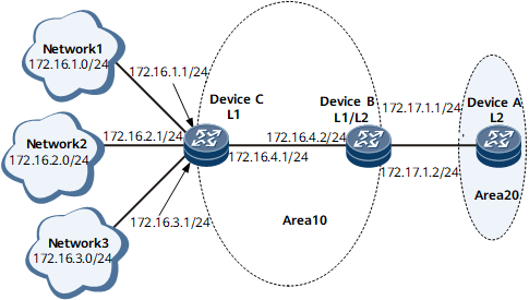
Figure 1 shows route summarization networking.
Device A, Device B, and Device C run IS-IS to communicate with each other.
Device A belongs to area 20. Device B and Device C belong to area 10.
Device A is a Level-2 device, Device B is a Level-1-2 device, and Device C is a Level-1 device.
Device B maintains both the Level-1 and Level-2 LSDBs. The routes to network segments 172.16.1.0/24, 172.16.2.0/24, and 172.16.3.0/24 in the Level-1 area can leak to the Level-2 area. If Device C's directly connected interface with the IP address 172.16.1.1/24 frequently alternates between up and down, the flapping is advertised to the Level-2 area. Frequent LSP flooding and SPF calculation on DeviceB consume a large number of CPU resources of Device B and may even cause network flapping.
To solve this problem, configure Device B to summarize routes to the three network segments into the route 172.16.0.0/16. This summarization reduces the number of routes to be maintained by Device B and prevents interface-state alteration in the Level-1 area from affecting route convergence in the Level-2 area.
Device Name |
Interface |
IP Address |
|---|---|---|
Device A |
GE 0/1/8 |
172.17.1.1/24 |
Device B |
GE 0/1/0 |
172.16.4.2/24 |
GE 0/1/8 |
172.17.1.2/24 |
|
Device C |
GE 0/1/0 |
172.16.4.1/24 |
Configuration Roadmap
The configuration roadmap is as follows:
Enable IS-IS on each router and check the IS-IS routing table.
Configure Device B to summarize routes and check the IS-IS routing table.
Data Preparation
To complete the configuration, you need area ID of Device A (20), area ID of Device B and Device C (10), and system IDs starting from 0000.0000.0001.
Procedure
- Configure an IP address for each interface. For configuration details, see Configuration Files in this section.
- Configure basic IS-IS functions.
# Configure Device A.
[~DeviceA] isis 1
[*DeviceA-isis-1] is-level level-2
[*DeviceA-isis-1] network-entity 20.0000.0000.0001.00
[*DeviceA-isis-1] quit
[*DeviceA] interface gigabitethernet 0/1/8
[*DeviceA-GigabitEthernet0/1/8] isis enable 1
[*DeviceA-GigabitEthernet0/1/8] commit
[~DeviceA-GigabitEthernet0/1/8] quit
# Configure Device B.
[~DeviceB] isis 1
[*DeviceB-isis-1] network-entity 10.0000.0000.0002.00
[*DeviceB-isis-1] quit
[*DeviceB] interface gigabitethernet 0/1/8
[*DeviceB-GigabitEthernet0/1/8] isis enable 1
[*DeviceB-GigabitEthernet0/1/8] quit
[*DeviceB] interface gigabitethernet 0/1/0
[*DeviceB-GigabitEthernet0/1/0] isis enable 1
[*DeviceB-GigabitEthernet0/1/0] commit
[~DeviceB-GigabitEthernet0/1/0] quit
# Configure Device C.
[~DeviceC] isis 1
[*DeviceC-isis-1] is-level level-1
[*DeviceC-isis-1] network-entity 10.0000.0000.0003.00
[*DeviceC-isis-1] quit
[*DeviceC] interface gigabitethernet 0/1/0
[*DeviceC-GigabitEthernet0/1/0] isis enable 1
[*DeviceC-GigabitEthernet0/1/0] commit
[~DeviceC-GigabitEthernet0/1/0] quit
The configurations of GE 0/1/8, GE 0/1/16, and GE 0/1/1 are similar to those of GE 0/1/0. For configuration details, see Configuration Files in this section.
# Display the IS-IS routing information on Device A.
[~DeviceA] display isis route
                         Route information for ISIS(1)
                         -----------------------------
                        ISIS(1) Level-2 Forwarding Table
                        --------------------------------
 IPV4 Destination     IntCost    ExtCost ExitInterface  NextHop          Flags
----------------------------------------------------------------------------
 172.16.1.0/24         30         NULL    GE0/1/8        172.17.1.2      A/-/L/-
 172.16.2.0/24         30         NULL    GE0/1/8        172.17.1.2      A/-/L/-
 172.16.3.0/24         30         NULL    GE0/1/8        172.17.1.2      A/-/L/-
 172.16.4.0/24         20         NULL    GE0/1/8        172.17.1.2      A/-/L/-
 172.17.1.0/24         10         NULL    GE0/1/8        Direct         D/-/L/-
     Flags: D-Direct, A-Added to URT, L-Advertised in LSPs, S-IGP Shortcut,
                               U-Up/Down Bit Set
     Protect Type: L-Link Protect, N-Node Protect
- Configure route summarization on Device B.
# Summarize route 172.16.1.0/24, 172.16.2.0/24, 172.16.3.0./24, and 172.16.4.0/24 into 172.16.0.0/16 on Device B.
[~DeviceB] isis 1
[~DeviceB-isis-1] summary 172.16.0.0 255.255.0.0 level-1-2
[*DeviceB-isis-1] commit
[~DeviceB-isis-1] quit
- Verify the configuration.
# Display the routing table of Device A. The following command output shows that routes 172.16.1.0/24, 172.16.2.0/24, 172.16.3.0/24, and 172.16.4.0/24 have been summarized into 172.16.0.0/16.
[~DeviceA] display isis route
                         Route information for ISIS(1)
                         -----------------------------
                        ISIS(1) Level-2 Forwarding Table
                        --------------------------------
 IPV4 Destination     IntCost    ExtCost ExitInterface   NextHop         Flags
----------------------------------------------------------------------------
 172.16.0.0/16         20         NULL    GE0/1/8        172.17.1.2      A/-/L/-
 172.17.1.0/24         10         NULL    GE0/1/8        Direct         D/-/L/-
     Flags: D-Direct, A-Added to URT, L-Advertised in LSPs, S-IGP Shortcut,
                               U-Up/Down Bit Set
     Protect Type: L-Link Protect, N-Node Protect
Configuration Files
Device A configuration file
#
 sysname DeviceA
#
isis 1
 is-level level-2
 network-entity 20.0000.0000.0001.00
#
interface GigabitEthernet0/1/8
 undo shutdown
 ip address 172.17.1.1 255.255.255.0
 isis enable 1
#
return
Device B configuration file
#
 sysname DeviceB
#
isis 1
 network-entity 10.0000.0000.0002.00
 summary 172.16.0.0 255.255.0.0 level-1-2
#
interface GigabitEthernet0/1/8
 undo shutdown
 ip address 172.17.1.2 255.255.255.0
 isis enable 1
#
interface GigabitEthernet0/1/0
 undo shutdown
 ip address 172.16.4.2 255.255.255.0
 isis enable 1
#
return
Device C configuration file
#
 sysname DeviceC
#
isis 1
 is-level level-1
 network-entity 10.0000.0000.0003.00
#
interface GigabitEthernet0/1/0
 undo shutdown
 ip address 172.16.4.1 255.255.255.0
 isis enable 1
#
interface GigabitEthernet0/1/8
 undo shutdown
 ip address 172.16.1.1 255.255.255.0
 isis enable 1
#
interface GigabitEthernet0/1/16
 undo shutdown
 ip address 172.16.2.1 255.255.255.0
 isis enable 1
#
interface GigabitEthernet0/1/1
 undo shutdown
 ip address 172.16.3.1 255.255.255.0
 isis enable 1
#
return