Example for Configuring an L2VPN to Access L3VPNs Through Sub-interfaces for QinQ Termination
This part describes how to configure an L2VPN to access multiple L3VPNs through sub-interfaces for QinQ VLAN tag termination.
Networking Requirements
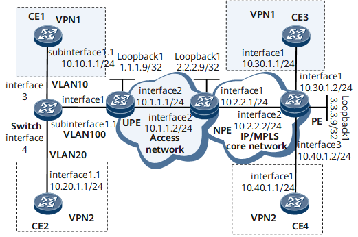
As shown in Figure 1, NPE and PE serve as the PE of the IP/MPLS backbone network; UPE serves as the PE of the VPWS access network. LDP is used as the signaling protocol to set up a VPWS between the UPE and the NPE.
CE1 and CE2 are two sites of the same user, and they carry different types of services. The inner VLAN tag 10 and 20 are used to distinguish the services. The user service packets are tagged with outer VLAN tag100 after convergence by the Switch. UPE sends the packets to NPE by using the specified VPWS on the access network according to the outer VLAN tag.
Create VE 0/1/8 and VE 0/1/9 on NPE. The VE 0/1/8 is the L2VE interface to terminate the VPWS, and the VE 0/1/9 is the L3VE interface to access the MPLS L3VPN. Create two VE sub-interfaces on VE 0/1/9. VE 0/1/9.1 terminates the QinQ user packets with inner VLAN tag as 10, and connects to VPN1; VE 0/1/9.2 terminates the QinQ user packets with an inner VLAN tag as 20, and connects to VPN2. Therefore, the ping operations between CE1 and CE3, and CE2 and CE4 succeed.

This example uses Virtual-Ethernet interface to configure L2VPN accessing L3VPN. As a VE interface is bound to only one board, when the board is faulty, services are interrupted. To improve service reliability, create two global virtual interfaces: Global-VE1 and Global-VE2. Global-VE1 is configured as an L2VE interface to terminate L2 services, and the Global-VE2 is configured as an L3VE interface to access an L3 network. Other configurations remain unchanged
Configuration Roadmap
The configuration roadmap is as follows:
Configure the MPLS L3VPN backbone network.
Create the L2VE interface on NPE to terminate the VPWS, and the L3VE interface to access L3VPN. Bind them to the same VE-Group.
To configure the LDP VPWS on the access network, perform the following procedures:
Configure routing protocols for devices (UPEs, P, and NPEs) on the access network to make them communicate, and enable MPLS.
The default tunnel policy is used, and LSPs are set up to transmit service data.
Enable MPLS L2VPN on the UPE and NPE, and establish VCs.
Enable Layer 2 forwarding and QinQ on the Switch.
Configure the access of CEs to MPLS L3VPN.
Data Preparation
To complete the configuration, you need the following data:
VE-Group number
IP addresses of VE interfaces
Names of VPN instances for MPLS L3VPN
Value of inner and outer VLAN tag of service packets
Procedure
- Configure an IP address for each interface. The configuration details are not mentioned here.
Configure the IP addresses for physical interfaces and the loopback interface according to Figure 1. The configuration details are not mentioned here.
- Create VE 0/1/8 and VE 0/1/9 on NPEs, and bind them to the same VE-Group.
# Create VE 0/1/8 to terminate the MPLS L2VPN.
<HUAWEI> system-view
[~HUAWEI] sysname NPE
[*HUAWEI] commit
[~NPE] interface virtual-ethernet0/1/8
[*NPE-Virtual-Ethernet0/1/8] ve-group 1 l2-terminate
[*NPE-Virtual-Ethernet0/1/8] quit
# Create VE 0/1/9 to access the MPLS L3VPN.
[~NPE] interface virtual-ethernet0/1/9
[*NPE-Virtual-Ethernet0/1/9] ve-group 1 l3-access
[*NPE-Virtual-Ethernet0/1/9] quit
[*NPE] commit
After the configuration is complete, run the display virtual-ethernet ve-group command. You can view the binding relationship between VE interfaces and a VE-Group.
[~NPE] display virtual-ethernet ve-group
 Ve-groupID    TerminateVE                   AccessVE
 1               Virtual-Ethernet0/1/8   Virtual-Ethernet0/1/9
Total 1, 1 printed
- Run an IGP on the VPWS access network. OSPF is used in the example. The configuration details are not mentioned here.
When configuring OSPF, advertise the 32-bit loopback interface addresses of the UPE and the NPE.
For more configurations, see "Configuration Files."
- Configure basic MPLS functions and LDP on the VPWS access network.
# Configure the UPE.
<HUAWEI> system-view
[~HUAWEI] sysname UPE
[*HUAWEI] commit
[~UPE] mpls lsr-id 1.1.1.9
[*UPE] mpls
[*UPE-mpls] quit
[*UPE] mpls ldp
[*UPE-mpls-ldp] quit
[*UPE] interface gigabitethernet 0/1/8
[*UPE-GigabitEthernet0/1/8] mpls
[*UPE-GigabitEthernet0/1/8] mpls ldp
[*UPE-GigabitEthernet0/1/8] undo shutdown
[*UPE-GigabitEthernet0/1/8] quit
[*UPE] commit
# Configure the NPE.
<HUAWEI> system-view
[~HUAWEI] sysname NPE
[*HUAWEI] commit
[~NPE] mpls lsr-id 2.2.2.9
[*NPE] mpls
[*NPE-mpls] quit
[*NPE] mpls ldp
[*NPE-mpls-ldp] quit
[*NPE] interface gigabitethernet 0/1/8
[*NPE-GigabitEthernet0/1/8] mpls
[*NPE-GigabitEthernet0/1/8] mpls ldp
[*NPE-GigabitEthernet0/1/8] undo shutdown
[*NPE-GigabitEthernet0/1/8] quit
[*NPE] commit
- Enable MPLS L2VPN on the PE and establish VCs.
# Configure the UPE.
[~UPE] mpls l2vpn
[*UPE-l2vpn] quit
[*UPE] interface gigabitethernet 0/1/0.1
[*UPE-GigabitEthernet0/1/0.1] shutdown
[*UPE-GigabitEthernet0/1/0.1] vlan-type dot1q 100
[*UPE-GigabitEthernet0/1/0.1] mpls l2vc 2.2.2.9 101
[*UPE-GigabitEthernet0/1/0.1] undo shutdown
[*UPE-GigabitEthernet0/1/0.1] quit
[*UPE] commit
# Configure the NPE.
[~NPE] mpls l2vpn
[*NPE-l2vpn] quit
[*NPE] interface virtual-ethernet0/1/8.1
[*NPE-Virtual-Ethernet0/1/8.1] vlan-type dot1q 100
[*NPE-Virtual-Ethernet0/1/8.1] mpls l2vc 1.1.1.9 101
[*NPE-Virtual-Ethernet0/1/8.1] quit
[*NPE] commit
After the configuration is complete, check the VPWS connections on the UPE and NPE. You can find one static L2VC.
Take the NPE as an example.
[~NPE] display mpls l2vc
Total ldp vc : 1     1 up       0 down
 *Client Interface          : Virtual-Ethernet0/1/8.1 is up
  Administrator PW          : no
  Session State             : up
  AC Status                 : up
  VC State                  : up
  VC ID                     : 101
  VC Type                   : vlan
  Destination               : 1.1.1.9
  local VC label            : 140288       remote VC label      : 140292
  control word              : disable
  remote control word       : disable
  forwarding entry          : exist
  local group ID            : 0
  remote group ID           : 0
  local AC OAM State        : up
  local PSN OAM State       : up
  local forwarding state    : forwarding
  local status code         : 0x0
  remote AC OAM state       : up
  remote PSN OAM state      : up
  remote forwarding state   : forwarding
  remote status code        : 0x0
  ignore standby state      : no
  BFD for PW                : unavailable
  VCCV State                : up
  manual fault              : not set
  active state              : active
  OAM Protocol           : --
  OAM Status             : --
  OAM Fault Type         : --
  PW APS ID              : --
  PW APS Status          : --
  TTL Value              : 1
  link state                : up
  local VC MTU              : 1500         remote VC MTU        : 1500
  local VCCV                : alert ttl lsp-ping bfd
  remote VCCV               : alert ttl lsp-ping bfd
  tunnel policy name        : --
  PW template name          : --
  primary or secondary      : primary
  load balance type         : flow
  Access-port               : false
  Switchover Flag           : false
  VC tunnel info            : 1 tunnels
    NO.0  TNL type          : ldp   , TNL ID : 0x0000000001004c4e42
  create time               : 0 days, 0 hours, 30 minutes, 18 seconds
  up time                   : 0 days, 0 hours, 0 minutes, 0 seconds
  last change time          : 0 days, 0 hours, 30 minutes, 18 seconds
  VC last up time           : 2012/07/24 12:31:31
  VC total up time          : 0 days, 2 hours, 12 minutes, 51 seconds
  CKey                      : 11
  NKey                      : 10
  PW redundancy mode        : frr
  AdminPw interface         : --
  AdminPw link state        : --
  Forward state             : send inactive, receive inactive
  Diffserv Mode             : uniform
  Service Class             : --
  Color                     : --
  DomainId                  : --
  Domain Name               : --
- Enable QinQ to add double tags for packets being sent to UPE by the Switch.
# Configure the Switch.
<HUAWEI> system-view
[~HUAWEI] sysname Switch
[*HUAWEI] commit
[~Switch] vlan 100
[*Switch-vlan100] quit
[*Switch] interface gigabitethernet 0/1/0
[*Switch-GigabitEthernet0/1/0] port trunk allow-pass vlan 100
[*Switch-GigabitEthernet0/1/0] quit
[*Switch] interface gigabitethernet 0/1/16
[*Switch-GigabitEthernet0/1/16] port vlan-stacking vlan 10 stack-vlan 100
[*Switch-GigabitEthernet0/1/16] quit
[*Switch] interface gigabitethernet 0/1/24
[*Switch-GigabitEthernet0/1/24] port vlan-stacking vlan 20 stack-vlan 100
[*Switch-GigabitEthernet0/1/24] quit
[*Switch] commit
# Configure CE1.
<HUAWEI> system-view
[~HUAWEI] sysname CE1
[*HUAWEI] commit
[~CE1] interface gigabitethernet 0/1/0.1
[*CE1-GigabitEthernet0/1/0.1] ip address 10.10.1.1 24
[*CE1-GigabitEthernet0/1/0.1] vlan-type dot1q 10
[*CE1-GigabitEthernet0/1/0.1] quit
[*CE1] commit
# Configure CE2.
<HUAWEI> system-view
[~HUAWEI] sysname CE2
[*HUAWEI] commit
[~CE2] interface gigabitethernet 0/1/0.1
[*CE2-GigabitEthernet0/1/0.1] ip address 10.20.1.1 24
[*CE2-GigabitEthernet0/1/0.1] vlan-type dot1q 20
[*CE2-GigabitEthernet0/1/0.1] quit
[*CE2] commit
- Run the IGP on the MPLS backbone network. IS-IS is used as the IGP protocol in this example. The configuration details are not mentioned here.
When configuring IS-IS, advertise the 32-bit loopback interface addresses of the PE and the NPE.
For more configurations, see "Configuration Files."
- Create VPN instances, and configure the CEs to access the instances.
# Configure the NPE.
[~NPE] ip vpn-instance VPN1
[*NPE-vpn-instance-VPN1] quit
[*NPE] ip vpn-instance VPN2
[*NPE-vpn-instance-VPN2] quit
[*NPE] interface virtual-ethernet0/1/9
[*NPE-Virtual-Ethernet0/1/9] quit
[*NPE] interface virtual-ethernet0/1/9.1
[*NPE-Virtual-Ethernet0/1/9.1] control-vid 1 qinq-termination
[*NPE-Virtual-Ethernet0/1/9.1] qinq termination pe-vid 100 ce-vid 10
[*NPE-Virtual-Ethernet0/1/9.1] ip binding vpn-instance VPN1
[*NPE-Virtual-Ethernet0/1/9.1] ip address 10.10.1.2 24
[*NPE-Virtual-Ethernet0/1/9.1] arp broadcast enable
[*NPE-Virtual-Ethernet0/1/9.1] quit
[*NPE] interface virtual-ethernet0/1/9.2
[*NPE-Virtual-Ethernet0/1/9.2] control-vid 1 qinq-termination
[*NPE-Virtual-Ethernet0/1/9.2] qinq termination pe-vid 100 ce-vid 20
[*NPE-Virtual-Ethernet0/1/9.2] ip binding vpn-instance VPN2
[*NPE-Virtual-Ethernet0/1/9.2] ip address 10.20.1.2 24
[*NPE-Virtual-Ethernet0/1/9.2] arp broadcast enable
[*NPE-Virtual-Ethernet0/1/9.2] quit
[*NPE] commit
# Configure the PE.
[~PE] ip vpn-instance VPN1
[*PE-vpn-instance-VPN1] quit
[*PE] ip vpn-instance VPN2
[*PE-vpn-instance-VPN2] quit
[*PE] interface gigabitethernet0/1/0
[*PE-GigabitEthernet0/1/0] ip binding vpn-instance VPN1
[*PE-GigabitEthernet0/1/0] ip address 10.30.1.2 24
[*PE-GigabitEthernet0/1/0] undo shutdown
[*PE-GigabitEthernet0/1/0] quit
[*PE] interface gigabitethernet0/1/16
[*PE-GigabitEthernet0/1/16] ip binding vpn-instance VPN2
[*PE-GigabitEthernet0/1/16] ip address 10.40.1.2 24
[*PE-GigabitEthernet0/1/16] undo shutdown
[*PE-GigabitEthernet0/1/16] quit
[*PE] commit
# Configure CE3.
<HUAWEI> system-view
[~HUAWEI] sysname CE3
[*HUAWEI] commit
[~CE3] interface gigabitethernet0/1/0
[*CE3-GigabitEthernet0/1/0] ip address 10.30.1.1 24
[*CE3-GigabitEthernet0/1/0] undo shutdown
[*CE3-GigabitEthernet0/1/0] quit
[*CE3] commit
# Configure CE4.
<HUAWEI> system-view
[~HUAWEI] sysname CE4
[*HUAWEI] commit
[~CE4] interface gigabitethernet0/1/0
[*CE4-GigabitEthernet0/1/0] ip address 10.40.1.1 24
[*CE4-GigabitEthernet0/1/0] undo shutdown
[*CE4-GigabitEthernet0/1/0] quit
[*CE4] commit
- Run OSPF between the PE and CE devices, and import the VPN routes.
# Configure the NPE.
[~NPE] ospf 100 vpn-instance VPN1
[*NPE-ospf-100] domain-id 10
[*NPE-ospf-100] import-route bgp
[*NPE-ospf-100] area 0
[*NPE-ospf-100-area-0.0.0.0] network 10.10.1.0 0.0.0.255
[*NPE-ospf-100-area-0.0.0.0] quit
[*NPE-ospf-100] quit
[*NPE] ospf 200 vpn-instance VPN2
[*NPE-ospf-200] domain-id 20
[*NPE-ospf-200] import-route bgp
[*NPE-ospf-200] area 0
[*NPE-ospf-200-area-0.0.0.0] network 10.20.1.0 0.0.0.255
[*NPE-ospf-200-area-0.0.0.0] quit
[*NPE-ospf-200] quit
[*NPE] bgp 100
[*NPE-bgp] ipv4-family vpn-instance VPN1
[*NPE-bgp-VPN1] import-route direct
[*NPE-bgp-VPN1] import-route ospf 100
[*NPE-bgp-VPN1] quit
[*NPE-bgp] ipv4-family vpn-instance VPN2
[*NPE-bgp-VPN2] import-route direct
[*NPE-bgp-VPN2] import-route ospf 200
[*NPE-bgp-VPN2] quit
[*NPE-bgp] quit
[*NPE] commit
# Configure CE1.
[~CE1] ospf 100
[*CE1-ospf-100] area 0
[*CE1-ospf-100-area-0.0.0.0] network 10.10.1.0 0.0.0.255
[*CE1-ospf-100-area-0.0.0.0] quit
[*CE1-ospf-100] quit
[*CE1] commit
# Configure CE2.
[~CE2] ospf 200
[*CE2-ospf-200] area 0
[*CE2-ospf-200-area-0.0.0.0] network 10.20.1.0 0.0.0.255
[*CE2-ospf-200-area-0.0.0.0] quit
[*CE2-ospf-200] quit
[*CE2] commit
# Configure the PE.
[~PE] ospf 100 vpn-instance VPN1
[*PE-ospf-100] domain-id 10
[*PE-ospf-100] import-route bgp
[*PE-ospf-100] area 0
[*PE-ospf-100-area-0.0.0.0] network 10.30.1.0 0.0.0.255
[*PE-ospf-100-area-0.0.0.0] quit
[*PE-ospf-100] quit
[*PE] ospf 200 vpn-instance VPN2
[*PE-ospf-200] domain-id 20
[*PE-ospf-200] import-route bgp
[*PE-ospf-200] area 0
[*PE-ospf-200-area-0.0.0.0] network 10.40.1.0 0.0.0.255
[*PE-ospf-200-area-0.0.0.0] quit
[*PE-ospf-200] quit
[*PE] bgp 100
[*PE-bgp] ipv4-family vpn-instance VPN1
[*PE-bgp-VPN1] import-route direct
[*PE-bgp-VPN1] import-route ospf 100
[*PE-bgp-VPN1] quit
[*PE-bgp] ipv4-family vpn-instance VPN2
[*PE-bgp-VPN2] import-route direct
[*PE-bgp-VPN2] import-route ospf 200
[*PE-bgp-VPN2] quit
[*PE-bgp] quit
[*PE] commit
# Configure CE3.
[~CE3] ospf 100
[*CE3-ospf-100] area 0
[*CE3-ospf-100-area-0.0.0.0] network 10.30.1.0 0.0.0.255
[*CE3-ospf-100-area-0.0.0.0] quit
[*CE3-ospf-100] quit
[*CE3] commit
# Configure CE4.
[~CE4] ospf 200
[*CE4-ospf-200] area 0
[*CE4-ospf-200-area-0.0.0.0] network 10.40.1.0 0.0.0.255
[*CE4-ospf-200-area-0.0.0.0] quit
[*CE4-ospf-200] quit
[*CE4] commit
- Set up MP-IBGP peer relationships between the NPE and PE.
# Configure the NPE.
[~NPE] bgp 100
[*NPE-bgp] peer 3.3.3.9 as-number 100
[*NPE-bgp] peer 3.3.3.9 connect-interface loopback 1
[*NPE-bgp] ipv4-family vpnv4
[*NPE-bgp-af-vpnv4] peer 3.3.3.9 enable
[*NPE-bgp-af-vpnv4] quit
[*NPE] commit
# Configure the PE.
[~PE] bgp 100
[*PE-bgp] peer 2.2.2.9 as-number 100
[*PE-bgp] peer 2.2.2.9 connect-interface loopback 1
[*PE-bgp] ipv4-family vpnv4
[*PE-bgp-af-vpnv4] peer 2.2.2.9 enable
[*PE-bgp-af-vpnv4] quit
[*PE] commit
After the configuration, run the display bgp peer command on the PE or the NPE. You can view that the BGP peer relationship between the PE and the NPE is set up and the status of the peer relationship is Established. Take the NPE as an example.
[~NPE] display bgp peer BGP local router ID : 2.2.2.9 Local AS number : 100 Total number of peers : 1 Peers in established state : 1 Peer V AS MsgRcvd MsgSent OutQ Up/Down State PrefRcv 3.3.3.9 4 100 2 6 0 00:00:12 Established 2 - Verify the configuration.
# Run the display ip routing-table vpn-instance command on the PE or the NPE. You can view the routes to the remote CE.
Take the NPE as an example.
[~NPE] display ip routing-table vpn-instance VPN1
Route Flags: R - relay, D - download to fib, T - to vpn-instance, B - black hole route
------------------------------------------------------------------------------
Routing Table: VPN1
         Destinations : 4        Routes : 4
Destination/Mask    Proto   Pre  Cost   Flags NextHop      Interface
10.10.1.0/24        Direct  0    0      D     10.10.1.2    Virtual-Ethernet0/1/9.1
10.10.1.2/32        Direct  0    0      D     127.0.0.1    InLoopBack0
10.30.1.0/24        IBGP    255  0      RD    3.3.3.9      GigabitEthernet0/1/0
255.255.255.255/32  Direct  0    0      D     127.0.0.1    InLoopBack0
[~NPE] display ip routing-table vpn-instance VPN2
Route Flags: R - relay, D - download to fib, T - to vpn-instance, B - black hole route
------------------------------------------------------------------------------
Routing Table: VPN2
         Destinations : 4        Routes : 4
Destination/Mask    Proto   Pre  Cost  Flags NextHop      Interface
10.20.1.0/24        Direct  0    0      D    10.20.1.2    Virtual-Ethernet0/1/9.2
10.20.1.2/32        Direct  0    0      D    127.0.0.1    InLoopBack0
10.40.1.0/24        IBGP    255  0      RD   3.3.3.9      GigabitEthernet0/1/0
255.255.255.255/32  Direct  0    0      D    127.0.0.1    InLoopBack0
# The ping operations between CE1 and CE3, and CE2 and CE4 succeed.
Take CE1 as example:
[~CE1] ping 10.30.1.1
  PING 10.30.1.1: 56  data bytes, press CTRL_C to break
    Reply from 10.30.1.1: bytes=56 Sequence=1 ttl=255 time=31 ms
    Reply from 10.30.1.1: bytes=56 Sequence=2 ttl=255 time=10 ms
    Reply from 10.30.1.1: bytes=56 Sequence=3 ttl=255 time=5 ms
    Reply from 10.30.1.1: bytes=56 Sequence=4 ttl=255 time=2 ms
    Reply from 10.30.1.1: bytes=56 Sequence=5 ttl=255 time=28 ms
  --- 10.30.1.1 ping statistics ---
    5 packet(s) transmitted
    5 packet(s) received
    0.00% packet loss
    round-trip min/avg/max = 2/15/31 ms
Configuration Files
Configuration file of the UPE
#
 sysname UPE
#
 mpls lsr-id 1.1.1.9
 mpls
#
 mpls l2vpn
#
mpls ldp
#
interface GigabitEthernet0/1/0
 undo shutdown
#
interface GigabitEthernet0/1/0.1
 vlan-type dot1q 100
 mpls l2vc 2.2.2.9 101
#
interface GigabitEthernet0/1/8
 undo shutdown
 ip address 10.1.1.1 255.255.255.0
 mpls
 mpls ldp
#
interface LoopBack1
 ip address 1.1.1.9 255.255.255.255
#
ospf 1
 area 0.0.0.0
  network 1.1.1.9 0.0.0.0
  network 10.1.1.0 0.0.0.255
#
return
Configuration file of the NPE
#
 sysname NPE
#
ip vpn-instance VPN1
 route-distinguisher 100:1
 apply-label per-instance
 vpn-target 111:1 export-extcommunity
 vpn-target 111:1 import-extcommunity
#
ip vpn-instance VPN2
 route-distinguisher 200:1
 apply-label per-instance
 vpn-target 222:1 export-extcommunity
 vpn-target 222:1 import-extcommunity
#
 mpls lsr-id 2.2.2.9
 mpls
#
 mpls l2vpn
#
mpls ldp
#
isis 1
 network-entity 10.0000.0000.0001.00
#
interface GigabitEthernet0/1/0
 undo shutdown
 ip address 10.1.1.1 255.255.255.0
 isis enable 1
 mpls
 mpls ldp
#
interface GigabitEthernet0/1/8
 undo shutdown
 ip address 10.1.1.2 255.255.255.0
 mpls
 mpls ldp
#
interface Virtual-Ethernet0/1/8
 ve-group 1 l2-terminate
#
interface Virtual-Ethernet0/1/8.1
 vlan-type dot1q 100
 mpls l2vc 1.1.1.9 101
#
interface Virtual-Ethernet0/1/9
 ve-group 1 l3-access
#
interface Virtual-Ethernet0/1/9.1
 encapsulation qinq-termination
 qinq termination pe-vid 100 ce-vid 10
 ip binding vpn-instance VPN1
 ip address 10.10.1.2 255.255.255.0
 arp broadcast enable
#
interface Virtual-Ethernet0/1/9.2
 encapsulation qinq-termination
 qinq termination pe-vid 100 ce-vid 20
 ip binding vpn-instance VPN2
 ip address 10.20.1.2 255.255.255.0
 arp broadcast enable
#
interface LoopBack1
 ip address 2.2.2.9 255.255.255.255
 isis enable 1
#
bgp 100
 peer 3.3.3.9 as-number 100
 peer 3.3.3.9 connect-interface LoopBack1
 #
 ipv4-family unicast
  undo synchronization
  peer 3.3.3.9 enable
#
 ipv4-family vpnv4
  policy vpn-target
  peer 3.3.3.9 enable
#
ipv4-family vpn-instance VPN1
  import-route ospf 100
  import-route direct
#
ipv4-family vpn-instance VPN2
  import-route ospf 200
  import-route direct
#
ospf 1
 area 0.0.0.0
  network 2.2.2.9 0.0.0.0
  network 10.1.1.0 0.0.0.255
#
ospf 100 vpn-instance VPN1
 import-route bgp
 domain-id 0.0.0.10
 area 0.0.0.0
  network 10.10.1.0 0.0.0.255
#
ospf 200 vpn-instance VPN2
 import-route bgp
 domain-id 0.0.0.20
 area 0.0.0.0
  network 10.20.1.0 0.0.0.255
#
return
Configuration file of the PE
#
 sysname PE
#
ip vpn-instance VPN1
 route-distinguisher 100:1
 apply-label per-instance
 vpn-target 111:1 export-extcommunity
 vpn-target 111:1 import-extcommunity
#
ip vpn-instance VPN2
 route-distinguisher 200:1
 apply-label per-instance
 vpn-target 222:1 export-extcommunity
 vpn-target 222:1 import-extcommunity
#
 mpls lsr-id 3.3.3.9
 mpls
#
mpls ldp
#
isis 1
 network-entity 10.0000.0000.0002.00
#
interface GigabitEthernet0/1/0
 undo shutdown
 ip binding vpn-instance VPN1
 ip address 10.30.1.2 255.255.255.0
#
interface GigabitEthernet0/1/0
 undo shutdown
 ip binding vpn-instance VPN2
 ip address 10.40.1.2 255.255.255.0
#
interface GigabitEthernet0/1/0
 undo shutdown
 ip address 10.1.1.2 255.255.255.0
 isis enable 1
 mpls
 mpls ldp
#
interface LoopBack1
 ip address 3.3.3.9 255.255.255.255
 isis enable 1
#
bgp 100
 peer 2.2.2.9 as-number 100
 peer 2.2.2.9 connect-interface LoopBack1
 #
 ipv4-family unicast
  undo synchronization
  peer 2.2.2.9 enable
#
 ipv4-family vpnv4
  policy vpn-target
  peer 2.2.2.9 enable
#
ipv4-family vpn-instance VPN1
  import-route ospf 100
  import-route direct
#
ipv4-family vpn-instance VPN2
  import-route ospf 200
  import-route direct
#
ospf 100 vpn-instance VPN1
 import-route bgp
 domain-id 0.0.0.10
 area 0.0.0.0
  network 10.30.1.0 0.0.0.255
#
ospf 200 vpn-instance VPN2
 import-route bgp
 domain-id 0.0.0.20
 area 0.0.0.0
  network 10.40.1.0 0.0.0.255
#
return
Configuration file of the Switch
#
 sysname Switch
#
 vlan batch 100
#
interface GigabitEthernet0/1/0
 undo shutdown
 port trunk allow-pass vlan 100
#
interface GigabitEthernet0/1/16
 undo shutdown
 port vlan-stacking vlan 10 stack-vlan 100
#
interface GigabitEthernet0/1/24
 undo shutdown
 port vlan-stacking vlan 20 stack-vlan 100
#
return
Configuration file of the CE1
#
 sysname CE1
#
interface GigabitEthernet0/1/0
 undo shutdown
#
interface GigabitEthernet0/1/0.1
 vlan-type dot1q 10
 ip address 10.10.1.1 255.255.255.0
#
ospf 100
 area 0.0.0.0
  network 10.10.1.0 0.0.0.255
#
return
Configuration file of the CE2
#
 sysname CE2
#
interface GigabitEthernet0/1/0
 undo shutdown
#
interface GigabitEthernet0/1/0.1
 vlan-type dot1q 20
 ip address 10.20.1.1 255.255.255.0
#
ospf 200
 area 0.0.0.0
  network 10.20.1.0 0.0.0.255
#
return
Configuration file of the CE3
#
 sysname CE3
#
interface GigabitEthernet0/1/0
 undo shutdown
 ip address 10.30.1.1 255.255.255.0
#
ospf 100
 area 0.0.0.0
  network 10.30.1.0 0.0.0.255
#
return
Configuration file of the CE4
#
 sysname CE4
#
interface GigabitEthernet0/1/0
 undo shutdown
 ip address 10.40.1.1 255.255.255.0
#
ospf 200
 area 0.0.0.0
  network 10.40.1.0 0.0.0.255
#
return