Example for Configuring PW APS-protected Static VPWS SS-PW Accessing L3VPN (IP RAN Scenario)
This section provides an example for configuring a static VPWS PW with PW APS protection on the L2VPN side to access an L3VPN.
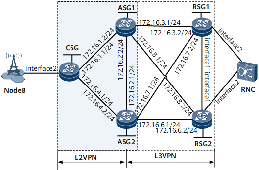
Networking Requirements

This chapter applies only to the NetEngine 8000 F1A.
This example uses Virtual-Ethernet interface to configure L2VPN accessing L3VPN. As a VE interface is bound to only one board, when the board is faulty, services are interrupted. To improve service reliability, create two global virtual interfaces: Global-VE1 and Global-VE2. Global-VE1 is configured as an L2VE interface to terminate L2VPN services, and the Global-VE2 is configured as an L3VE interface to access an L3VPN network. Other configurations remain unchanged
- In this example, interface1 and interface2 represent GE0/1/0 and GE0/1/3, respectively.
Device |
Interface |
Peer Device |
IP Address |
|---|---|---|---|
CSG |
GE0/1/1 |
ASG1 |
172.16.1.1/24 |
GE0/1/2 |
ASG2 |
172.16.4.1/24 |
|
GE0/1/3 |
NodeB |
- |
|
ASG1 |
GE0/1/0 |
ASG2 |
172.16.2.2/24 |
GE0/1/1 |
CSG |
172.16.1.2/24 |
|
GE0/1/3 |
RSG1 |
172.16.3.1/24 |
|
GE0/1/4 |
RSG2 |
172.16.8.1/24 |
|
ASG2 |
GE0/1/0 |
ASG1 |
172.16.2.1/24 |
GE0/1/2 |
CSG |
172.16.4.2/24 |
|
GE0/1/3 |
RSG2 |
172.16.6.1/24 |
|
GE0/1/4 |
RSG1 |
172.16.7.1/24 |
|
RSG1 |
GE0/1/0 |
RSG2 |
- |
GE0/1/1 |
ASG1 |
172.16.3.2/24 |
|
GE0/1/2 |
ASG2 |
172.16.7.2/24 |
|
GE0/1/3 |
RNC |
- |
|
RSG2 |
GE0/1/0 |
RSG1 |
- |
GE0/1/1 |
ASG2 |
172.16.6.2/24 |
|
GE0/1/2 |
ASG1 |
172.16.8.2/24 |
|
GE0/1/3 |
RNC |
- |
Configuration Roadmap
The configuration roadmap is as follows:
- Configure IP addresses on each device.
- Configure IGP routes on each device.
- Configure MPLS and public network tunnels. Specifically:
- Configure a static bidirectional co-routed LSP between the CSG and ASG1, between the CSG and ASG2, and between ASG1 and ASG2.
- Configure LSPs between ASGs and RSGs.
- Configure static VPWS on the CSG and ASGs.
- Configure PW APS on the CSG and ASGs.
Configure an L3VPN.
- Configure VPN instances on ASGs and RSGs.
- Configure a VE group on each ASG, and bind the L3VE sub-interface in the group to the VPN instance on each ASG.
- Establish MP-IBGP peer relationships between ASGs and RSGs.
- Import direct routes to VPN instances on ASGs and RSGs.
- Configure VPN FRR.
Data Preparation
To complete the configuration, you need the following data:
Interface numbers, interface IP addresses, and OSPF process IDs
L2VCs' destination IP addresses, VC IDs, and VC types
Names, local discriminators, and remote discriminators of BFD sessions
VE group number
Numbers and priorities of VRRP groups
Procedure
- Configure IP addresses for the CSG, ASGs, and RSGs. For configuration details, see Configuration Files in this section.
- Configure an IGP on the CSG, ASGs, and RSGs. In this example, OSPF is used.
# Configure the CSG.
<CSG> system-view
[~CSG] ospf 1
[*CSG-ospf-1] area 0
[*CSG-ospf-1-area-0.0.0.0] network 1.1.1.1 0.0.0.0
[*CSG-ospf-1-area-0.0.0.0] network 172.16.1.0 0.0.0.255
[*CSG-ospf-1-area-0.0.0.0] network 172.16.4.0 0.0.0.255
[*CSG-ospf-1-area-0.0.0.0] quit
[*CSG-ospf-1] quit
[*CSG] commit
# Configure ASG1.
<ASG1> system-view
[~ASG1] ospf 1
[*ASG1-ospf-1] area 0
[*ASG1-ospf-1-area-0.0.0.0] network 2.2.2.2 0.0.0.0
[*ASG1-ospf-1-area-0.0.0.0] network 172.16.1.0 0.0.0.255
[*ASG1-ospf-1-area-0.0.0.0] network 172.16.2.0 0.0.0.255
[*ASG1-ospf-1-area-0.0.0.0] network 172.16.3.0 0.0.0.255
[*ASG1-ospf-1-area-0.0.0.0] network 172.16.8.0 0.0.0.255
[*ASG1-ospf-1-area-0.0.0.0] quit
[*ASG1-ospf-1] quit
[*ASG1] commit
# Configure ASG2.
<ASG2> system-view
[~ASG2] ospf 1
[*ASG2-ospf-1] area 0
[*ASG2-ospf-1-area-0.0.0.0] network 3.3.3.3 0.0.0.0
[*ASG2-ospf-1-area-0.0.0.0] network 172.16.2.0 0.0.0.255
[*ASG2-ospf-1-area-0.0.0.0] network 172.16.4.0 0.0.0.255
[*ASG2-ospf-1-area-0.0.0.0] network 172.16.6.0 0.0.0.255
[*ASG2-ospf-1-area-0.0.0.0] network 172.16.7.0 0.0.0.255
[*ASG2-ospf-1-area-0.0.0.0] quit
[*ASG2-ospf-1] quit
[*ASG2] commit
# Configure RSG1.
<RSG1> system-view
[~RSG1] ospf 1
[*RSG1-ospf-1] area 0
[*RSG1-ospf-1-area-0.0.0.0] network 4.4.4.4 0.0.0.0
[*RSG1-ospf-1-area-0.0.0.0] network 172.16.3.0 0.0.0.255
[*RSG1-ospf-1-area-0.0.0.0] network 172.16.7.0 0.0.0.255
[*RSG1-ospf-1-area-0.0.0.0] quit
[*RSG1-ospf-1] quit
[*RSG1] commit
# Configure RSG2.
<RSG2> system-view
[~RSG2] ospf 1
[*RSG2-ospf-1] area 0
[*RSG2-ospf-1-area-0.0.0.0] network 5.5.5.5 0.0.0.0
[*RSG2-ospf-1-area-0.0.0.0] network 172.16.6.0 0.0.0.255
[*RSG2-ospf-1-area-0.0.0.0] network 172.16.8.0 0.0.0.255
[*RSG2-ospf-1-area-0.0.0.0] quit
[*RSG2-ospf-1] quit
[*RSG2] commit
After completing the configurations, check OSPF route information. The following example uses the command output on ASG1.
[~ASG1] display ospf routing OSPF Process 1 with Router ID 172.16.1.2 Routing Tables Routing for Network Destination Cost Type NextHop AdvRouter Area 1.1.1.1/32 1 Stub 172.16.1.1 172.16.1.1 0.0.0.0 2.2.2.2/32 0 Direct 2.2.2.2 172.16.1.2 0.0.0.0 3.3.3.3/32 1 Stub 172.16.2.1 172.16.4.2 0.0.0.0 172.16.1.0/24 1 Direct 172.16.1.2 172.16.1.2 0.0.0.0 172.16.2.0/24 1 Direct 172.16.2.2 172.16.1.2 0.0.0.0 172.16.4.0/24 2 Transit 172.16.1.1 172.16.1.1 0.0.0.0 172.16.4.0/24 2 Transit 172.16.2.1 172.16.1.1 0.0.0.0 Total Nets: 6 Intra Area: 6 Inter Area: 0 ASE: 0 NSSA: 0 - Configure basic MPLS functions and public network tunnels.
- Configure a static PW protection group.
# Configure a pair of primary and secondary static PWs on the CSG.
[~CSG] mpls l2vpn
[*CSG-l2vpn] quit
[*CSG] interface gigabitethernet0/1/3.1
[*CSG-GigabitEthernet0/1/3.1] vlan-type dot1q 10
[*CSG-GigabitEthernet0/1/3.1] mpls static-l2vc destination 2.2.2.2 1 transmit-vpn-label 100 receive-vpn-label 200
[*CSG-GigabitEthernet0/1/3.1] mpls static-l2vc destination 3.3.3.3 2 transmit-vpn-label 300 receive-vpn-label 400 secondary
[*CSG-GigabitEthernet0/1/3.1] quit
[*CSG] commit
# Configure the primary and bypass PWs on ASG1.
[~ASG1] mpls l2vpn
[*ASG1-l2vpn] quit
[*ASG1] interface virtual-ethernet 0/1/0
[*ASG1-Virtual-Ethernet0/1/0] ve-group 1 l2-terminate
[*ASG1-Virtual-Ethernet0/1/0] quit
[*ASG1] interface virtual-ethernet 0/1/0.1
[*ASG1-Virtual-Ethernet0/1/0.1] vlan-type dot1q 10
[*ASG1-Virtual-Ethernet0/1/0.1] mpls static-l2vc destination 1.1.1.1 1 transmit-vpn-label 200 receive-vpn-label 100
[*ASG1-Virtual-Ethernet0/1/0.1] mpls static-l2vc destination 3.3.3.3 3 transmit-vpn-label 500 receive-vpn-label 600 bypass
[*ASG1-Virtual-Ethernet0/1/0.1] quit
[*ASG1] commit
# Configure the secondary and bypass PWs on ASG2.
[~ASG2] mpls l2vpn
[*ASG2-l2vpn] quit
[*ASG2] interface virtual-ethernet 0/1/0
[*ASG2-Virtual-Ethernet0/1/0] ve-group 1 l2-terminate
[*ASG1-Virtual-Ethernet0/1/0] quit
[*ASG2] interface virtual-ethernet 0/1/0.1
[*ASG2-Virtual-Ethernet0/1/0.1] vlan-type dot1q 10
[*ASG2-Virtual-Ethernet0/1/0.1] mpls static-l2vc destination 1.1.1.1 2 transmit-vpn-label 400 receive-vpn-label 300
[*ASG2-Virtual-Ethernet0/1/0.1] mpls static-l2vc destination 2.2.2.2 3 transmit-vpn-label 600 receive-vpn-label 500 bypass
[*ASG2-Virtual-Ethernet0/1/0.1] quit
[*ASG2] commit
- Configure PW APS on the CSG and ASGs.
# Configure the CSG.
[~CSG] pw-aps 1
[*CSG-pw-aps-1] quit
[*CSG] interface gigabitethernet0/1/3.1
[*CSG-GigabitEthernet0/1/3.1] mpls l2vpn pw-aps 1 admin
[*CSG-GigabitEthernet0/1/3.1] quit
[*CSG] commit
# Configure ASG1.
[~ASG1] pw-aps 1
[*ASG1-pw-aps-1] role slave
[*ASG1-pw-aps-1] remote-aps 1
[*ASG1-pw-aps-1] quit
[*ASG1] interface virtual-ethernet 0/1/0.1
[*ASG1-Virtual-Ethernet0/1/0.1] mpls l2vpn pw-aps 1 admin
[*ASG1-Virtual-Ethernet0/1/0.1] quit
[*ASG1] commit
# Configure ASG2.
[~ASG2] pw aps 1
[*ASG2-pw-aps-1] role master
[*ASG2-pw-aps-1] remote-aps 1
[*ASG2-pw-aps-1] quit
[*ASG2] interface virtual-ethernet 0/1/0.1
[*ASG2-Virtual-Ethernet0/1/0.1] mpls l2vpn pw-aps 1 admin
[*ASG2-Virtual-Ethernet0/1/0.1] quit
[*ASG2] commit
- Configure MPLS OAM to detect PW status.
# Configure the CSG.
[~CSG] mpls
[*CSG-mpls] mpls oam
[*CSG-mpls] quit
[*CSG] mpls-oam
[*CSG-mpls-oam] mpls oam l2vc peer-ip 2.2.2.2 vc-id 1 vc-type vlan type cv
[*CSG-mpls-oam] mpls oam l2vc peer-ip 2.2.2.2 vc-id 2 vc-type vlan type cv
[*CSG-mpls-oam] mpls oam l2vc enable receive peer-ip 2.2.2.2 vc-id 1 vc-type vlan
[*CSG-mpls-oam] mpls oam l2vc enable receive peer-ip 3.3.3.3 vc-id 2 vc-type vlan
[*CSG-mpls-oam] mpls oam l2vc enable send peer-ip 2.2.2.2 vc-id 1 vc-type vlan
[*CSG-mpls-oam] mpls oam l2vc enable send peer-ip 3.3.3.3 vc-id 2 vc-type vlan
[*CSG-mpls-oam] quit
[*CSG] commit
# Configure ASG1.
[~ASG1] mpls
[*ASG1-mpls] mpls oam
[*ASG1-mpls] quit
[*ASG1] mpls-oam
[*ASG1-mpls-oam] mpls oam l2vc peer-ip 1.1.1.1 vc-id 1 vc-type vlan type cv
[*ASG1-mpls-oam] mpls oam l2vc peer-ip 3.3.3.3 vc-id 3 vc-type vlan type cv
[*ASG1-mpls-oam] mpls oam l2vc enable receive peer-ip 1.1.1.1 vc-id 1 vc-type vlan
[*ASG1-mpls-oam] mpls oam l2vc enable receive peer-ip 3.3.3.3 vc-id 3 vc-type vlan
[*ASG1-mpls-oam] mpls oam l2vc enable send peer-ip 1.1.1.1 vc-id 1 vc-type vlan
[*ASG1-mpls-oam] mpls oam l2vc enable send peer-ip 3.3.3.3 vc-id 3 vc-type vlan
[*ASG1-mpls-oam] quit
[*ASG1] commit
# Configure ASG2.
[~ASG2] mpls
[*ASG2-mpls] mpls oam
[*ASG2-mpls] quit
[*ASG2] mpls-oam
[*ASG2-mpls-oam] mpls oam l2vc peer-ip 1.1.1.1 vc-id 2 vc-type vlan type cv
[*ASG2-mpls-oam] mpls oam l2vc peer-ip 2.2.2.2 vc-id 3 vc-type vlan type cv
[*ASG2-mpls-oam] mpls oam l2vc enable receive peer-ip 1.1.1.1 vc-id 2 vc-type vlan
[*ASG2-mpls-oam] mpls oam l2vc enable receive peer-ip 2.2.2.2 vc-id 3 vc-type vlan
[*ASG2-mpls-oam] mpls oam l2vc enable send peer-ip 1.1.1.1 vc-id 2 vc-type vlan
[*ASG2-mpls-oam] mpls oam l2vc enable send peer-ip 2.2.2.2 vc-id 3 vc-type vlan
[*ASG2-mpls-oam] quit
[*ASG2] commit
Check MPLS OAM information on PE1.
[~PE1] display mpls oam l2vc all -------------------------------------------------------------------------------- Total Oam Num: 2 Total Start Oam Num: 2 Total Defect Oam Num: 0 -------------------------------------------------------------------------------- No. Peer IP VC Type VC ID Status -------------------------------------------------------------------------------- 1 2.2.2.2 vlan 1 Start/Non-defect 2 3.3.3.3 vlan 2 Start/Non-defect - Configure an L3VPN.
- For details about how to configure VRRP on ASG1 and ASG2, see Configuration Files in this section.
- For details about how to configure VRRP on each RSG, see Configuration Files in this section.
Configuration Files
CSG configuration file
#
sysname CSG
#
mpls lsr-id 1.1.1.1
#
mpls
 mpls te
 mpls oam
#
bidirectional static-cr-lsp ingress Tunnel10
 forward outgoing-interface GigabitEthernet0/1/1 nexthop 172.16.1.2 out-label 20
 backward in-label 30 lsrid 2.2.2.2 tunnel-id 100
#
bidirectional static-cr-lsp ingress Tunnel11
 forward outgoing-interface GigabitEthernet0/1/2 nexthop 172.16.4.2 out-label 40
 backward in-label 50 lsrid 3.3.3.3 tunnel-id 200
#
mpls l2vpn
#
pw-aps 1
#
interface GigabitEthernet0/1/1
 undo shutdown
 ip address 172.16.1.1 255.255.255.0
 mpls
 mpls te
#
interface GigabitEthernet0/1/2
 undo shutdown
 ip address 172.16.4.1 255.255.255.0
 mpls
 mpls te
#
interface GigabitEthernet0/1/3
 undo shutdown
#
interface GigabitEthernet0/1/3.1
 vlan-type dot1q 10
 mpls static-l2vc destination 2.2.2.2 1 transmit-vpn-label 100 receive-vpn-label 200
  mpls static-l2vc destination 3.3.3.3 2 transmit-vpn-label 300 receive-vpn-label 400 secondary
 mpls l2vpn pw-aps 1 admin
#
interface LoopBack0
 ip address 1.1.1.1 255.255.255.255
#
interface Tunnel10
 ip address unnumbered interface LoopBack0
 tunnel-protocol mpls te
 destination 2.2.2.2
 mpls te signal-protocol cr-static
 mpls te tunnel-id 100
 mpls te bidirectional
#
interface Tunnel11
 ip address unnumbered interface LoopBack0
 tunnel-protocol mpls te
 destination 3.3.3.3
 mpls te signal-protocol cr-static
 mpls te tunnel-id 200
 mpls te bidirectional
#
ospf 1
 area 0.0.0.0
  network 1.1.1.1 0.0.0.0
  network 172.16.1.0 0.0.0.255
  network 172.16.4.0 0.0.0.255
#
mpls-oam
 mpls oam l2vc peer-ip 2.2.2.2 vc-id 1 vc-type vlan type cv
 mpls oam l2vc enable send peer-ip 2.2.2.2 vc-id 1 vc-type vlan
 mpls oam l2vc enable receive peer-ip 2.2.2.2 vc-id 1 vc-type vlan
 mpls oam l2vc peer-ip 3.3.3.3 vc-id 2 vc-type vlan type cv
 mpls oam l2vc enable send peer-ip 3.3.3.3 vc-id 2 vc-type vlan
 mpls oam l2vc enable receive peer-ip 3.3.3.3 vc-id 2 vc-type vlan
#
return
ASG1 configuration file
#
sysname ASG1
#
ip vpn-instance vpna
 ipv4-family
  route-distinguisher 1:1
  apply-label per-instance
  vpn frr
  vpn-target 1:1 export-extcommunity
  vpn-target 1:1 import-extcommunity
#
mpls lsr-id 2.2.2.2
#
mpls
 mpls te
 mpls oam
#
bidirectional static-cr-lsp egress Tunnel11
 forward in-label 20 lsrid 1.1.1.1 tunnel-id 100
 backward outgoing-interface GigabitEthernet0/1/1 nexthop 172.16.1.1 out-label 30
 mpls l2vpn
#
bidirectional static-cr-lsp ingress Tunnel12
 forward outgoing-interface GigabitEthernet0/1/2 nexthop 172.16.2.1 out-label 60
 backward in-label 70 lsrid 3.3.3.3 tunnel-id 300
#
mpls l2vpn
#
pw-aps 1
 role slave
 remote-aps 1
#
mpls ldp
#
interface GigabitEthernet0/1/0
 undo shutdown
 mpls
 mpls te
#
interface GigabitEthernet0/1/1
 undo shutdown
 ip address 172.16.1.2 255.255.255.0
 mpls
 mpls te
 mpls rsvp-te
 mpls rsvp-te hello
#
interface GigabitEthernet0/1/3
 undo shutdown
 ip address 172.16.3.1 255.255.255.0
 mpls
 mpls ldp
#
interface GigabitEthernet0/1/4
 undo shutdown
 ip address 172.16.8.1 255.255.255.0
 mpls
 mpls ldp
#
interface LoopBack0
 ip address 2.2.2.2 255.255.255.255
#
interface Tunnel10
 ip address unnumbered interface LoopBack0
 tunnel-protocol mpls te
 destination 1.1.1.1
 mpls te signal-protocol cr-static
 mpls te tunnel-id 100
 mpls te passive-tunnel
 mpls te binding bidirectional static-cr-lsp egress Tunnel10
#
interface Tunnel12
 ip address unnumbered interface LoopBack0
 tunnel-protocol mpls te
 destination 3.3.3.3
 mpls te signal-protocol cr-static
 mpls te tunnel-id 300
 mpls te bidirectional
#
interface Virtual-Ethernet0/1/0
 ve-group 1 l2-terminate
#
interface Virtual-Ethernet0/1/0.1
 vlan-type dot1q 10
 mpls static-l2vc destination 1.1.1.1 1 transmit-vpn-label 200 receive-vpn-label 100
 mpls static-l2vc destination 3.3.3.3 3 transmit-vpn-label 500 receive-vpn-label 600 bypass
 mpls l2vpn pw-aps 1 admin
#
interface Virtual-Ethernet0/1/1
 ve-group 1 l3-access
#
interface Virtual-Ethernet0/1/1.1
 vlan-type dot1q 10
 ip binding vpn-instance vpna
 ip address 10.10.1.2 255.255.255.0
 direct-route track pw-state degrade-cost 30
 vrrp vrid 10 virtual-ip 10.10.1.3
 vrrp vrid 10 track admin-vrrp interface GigabitEthernet0/1/0 vrid 20
#
bgp 100
 graceful-restart
 peer 3.3.3.3 as-number 100
 peer 3.3.3.3 connect-interface LoopBack0
 peer 4.4.4.4 as-number 100
 peer 4.4.4.4 connect-interface LoopBack0
 peer 5.5.5.5 as-number 100
 peer 5.5.5.5 connect-interface LoopBack0
 #
 ipv4-family unicast
 peer 3.3.3.3 enable
  peer 4.4.4.4 enable
  peer 5.5.5.5 enable
 #
 ipv4-family vpnv4
  policy vpn-target
  peer 3.3.3.3 enable
  peer 4.4.4.4 enable
  peer 5.5.5.5 enable
 #
 ipv4-family vpn-instance vpna
  import-route direct
#
ospf 1
 area 0.0.0.0
  network 2.2.2.2 0.0.0.0
  network 172.16.1.0 0.0.0.255
  network 172.16.3.0 0.0.0.255
  network 172.16.2.0 0.0.0.255
  network 172.16.8.0 0.0.0.255
#
mpls-oam
 mpls oam l2vc peer-ip 1.1.1.1 vc-id 1 vc-type vlan type cv
 mpls oam l2vc enable send peer-ip 2.2.2.2 vc-id 1 vc-type vlan
 mpls oam l2vc enable receive peer-ip 2.2.2.2 vc-id 1 vc-type vlan
 mpls oam l2vc peer-ip 3.3.3.3 vc-id 3 vc-type vlan type cv
 mpls oam l2vc enable send peer-ip 3.3.3.3 vc-id 3 vc-type vlan
 mpls oam l2vc enable receive peer-ip 3.3.3.3 vc-id 3 vc-type vlan
#
return
ASG2 configuration file
#
sysname ASG2
#
ip vpn-instance vpna
 ipv4-family
  route-distinguisher 1:1
  apply-label per-instance
  vpn frr
  vpn-target 1:1 export-extcommunity
  vpn-target 1:1 import-extcommunity
#
mpls lsr-id 3.3.3.3
#
mpls
 mpls te
 mpls oam
#
bidirectional static-cr-lsp egress Tunnel11
 forward in-label 40 lsrid 1.1.1.1 tunnel-id 200
 backward outgoing-interface GigabitEthernet0/1/2 nexthop 172.16.4.1 out-label 50
#
bidirectional static-cr-lsp egress Tunnel12
 forward in-label 60 lsrid 2.2.2.2 tunnel-id 300
 backward outgoing-interface GigabitEthernet0/1/0 nexthop 172.16.2.2 out-label 70
#
mpls l2vpn
#
pw-aps 1
 role master
 remote-aps 1
#
mpls ldp
#
interface GigabitEthernet0/1/0
 undo shutdown
 ip address 172.16.2.1 255.255.255.0
 mpls
 mpls te
#
interface GigabitEthernet0/1/2
 undo shutdown
 ip address 172.16.4.2 255.255.255.0
 mpls
 mpls te
#
interface GigabitEthernet0/1/3
 undo shutdown
 ip address 172.16.6.1 255.255.255.0
 mpls
 mpls ldp
#
interface GigabitEthernet0/1/4
 undo shutdown
 ip address 172.16.7.1 255.255.255.0
 mpls
 mpls ldp
#
interface LoopBack0
 ip address 3.3.3.3 255.255.255.255
#
interface Tunnel11
 ip address unnumbered interface LoopBack0
 tunnel-protocol mpls te
 destination 1.1.1.1
 mpls te signal-protocol cr-static
 mpls te tunnel-id 200
 mpls te passive-tunnel
 mpls te binding bidirectional static-cr-lsp egress Tunnel11
#
interface Tunnel12
 ip address unnumbered interface LoopBack0
 tunnel-protocol mpls te
 destination 2.2.2.2
 mpls te signal-protocol cr-static
 mpls te tunnel-id 300
 mpls te passive-tunnel
 mpls te binding bidirectional static-cr-lsp egress Tunnel12
#
interface Virtual-Ethernet0/1/0
 ve-group 1 l2-terminate
#
interface Virtual-Ethernet0/1/0.1
 vlan-type dot1q 10
mpls static-l2vc destination 1.1.1.1 2 transmit-vpn-label 400 receive-vpn-label 300
 mpls static-l2vc destination 2.2.2.2 3 transmit-vpn-label 600 receive-vpn-label 500 bypass
 mpls l2vpn pw-aps 1 admin
#
interface Virtual-Ethernet0/1/1
 ve-group 1 l3-access
#
interface Virtual-Ethernet0/1/1.1
 vlan-type dot1q 10
 ip binding vpn-instance vpna
 ip address 10.10.1.4 255.255.255.0
 vrrp vrid 10 virtual-ip 10.10.1.3
 vrrp vrid 10 track admin-vrrp interface GigabitEthernet0/1/0 vrid 20
#
bgp 100
 graceful-restart
 peer 2.2.2.2 as-number 100
 peer 2.2.2.2 connect-interface LoopBack0
 peer 4.4.4.4 as-number 100
 peer 4.4.4.4 connect-interface LoopBack0
 peer 5.5.5.5 as-number 100
 peer 5.5.5.5 connect-interface LoopBack0
#
ipv4-family unicast
 undo synchronization
 peer 2.2.2.2 enable
 peer 4.4.4.4 enable
 peer 5.5.5.5 enable
#
ipv4-family vpnv4
 policy vpn-target
 peer 2.2.2.2 enable
 peer 4.4.4.4 enable
 peer 5.5.5.5 enable
#
ipv4-family vpn-instance vpna
 import-route direct
#
ospf 1
 area 0.0.0.0
  network 3.3.3.3 0.0.0.0
  network 172.16.2.0 0.0.0.255
  network 172.16.7.0 0.0.0.255
  network 172.16.4.0 0.0.0.255
  network 172.16.6.0 0.0.0.255
#
mpls-oam
 mpls oam l2vc peer-ip 1.1.1.1 vc-id 2 vc-type vlan type cv
 mpls oam l2vc enable send peer-ip 1.1.1.1 vc-id 2 vc-type vlan
 mpls oam l2vc enable receive peer-ip 1.1.1.1 vc-id 2 vc-type vlan
 mpls oam l2vc peer-ip 2.2.2.2 vc-id 3 vc-type vlan type cv
 mpls oam l2vc enable send peer-ip 2.2.2.2 vc-id 3 vc-type vlan
 mpls oam l2vc enable receive peer-ip 2.2.2.2 vc-id 3 vc-type vlan
#
return
RSG1 configuration file
#
sysname RSG1
#
vlan batch 10
#
ip vpn-instance vpna
 ipv4-family
  route-distinguisher 1:1
  apply-label per-instance
  vpn frr
  vpn-target 1:1 export-extcommunity
  vpn-target 1:1 import-extcommunity
#
mpls lsr-id 4.4.4.4
#
 mpls l2vpn
#
mpls ldp
#
interface Vlanif10
 ip binding vpn-instance vpna
 ip address 10.0.1.1 255.255.255.0
 vrrp vrid 1 virtual-ip 10.0.1.3
 vrrp vrid 1 priority 150
#
interface GigabitEthernet0/1/0
 portswitch
 undo shutdown
 port link-type trunk
 port trunk allow-pass vlan 10
#
interface GigabitEthernet0/1/1
 undo shutdown
 ip address 172.16.3.2 255.255.255.0
 mpls
 mpls ldp
#
interface GigabitEthernet0/1/2
 undo shutdown
 ip address 172.16.7.2 255.255.255.0
 mpls
 mpls ldp
#
interface GigabitEthernet0/1/3
 portswitch
 undo shutdown
 port link-type trunk
 port trunk allow-pass vlan 10
#
interface LoopBack0
 ip address 4.4.4.4 255.255.255.255
#
bgp 100
 graceful-restart
 peer 2.2.2.2 as-number 100
 peer 2.2.2.2 connect-interface LoopBack0
 peer 3.3.3.3 as-number 100
 peer 3.3.3.3 connect-interface LoopBack0
 peer 5.5.5.5 as-number 100
 peer 5.5.5.5 connect-interface LoopBack0
#
ipv4-family unicast
 undo synchronization
 peer 2.2.2.2 enable
 peer 3.3.3.3 enable
 peer 5.5.5.5 enable
#
ipv4-family vpnv4
 policy vpn-target
 peer 2.2.2.2 enable
 peer 3.3.3.3 enable
 peer 5.5.5.5 enable
#
ipv4-family vpn-instance vpna
 import-route direct
#
ospf 100
 area 0.0.0.0
  network 4.4.4.4 0.0.0.0
  network 172.16.3.0 0.0.0.255
  network 172.16.7.0 0.0.0.255
  mpls-te enable
#
return
RSG2 configuration file
#
sysname RSG2
#
vlan batch 10
#
ip vpn-instance vpna
 ipv4-family
  route-distinguisher 11
  apply-label per-instance
  vpn frr
  vpn-target 11 export-extcommunity
  vpn-target 11 import-extcommunity
#
mpls lsr-id 5.5.5.5
#
mpls l2vpn
#
mpls ldp
#
interface Vlanif10
 ip binding vpn-instance vpna
 ip address 10.0.1.2 255.255.255.0
 vrrp vrid 1 virtual-ip 10.0.1.3
#
interface GigabitEthernet0/1/0
 portswitch
 undo shutdown
 port link-type trunk
 port trunk allow-pass vlan 10
#
interface GigabitEthernet0/1/1
 undo shutdown
 ip address 172.16.6.2 255.255.255.0
 mpls
 mpls ldp
#
interface GigabitEthernet0/1/2
 undo shutdown
 ip address 172.16.8.2 255.255.255.0
 mpls
 mpls ldp
#
interface GigabitEthernet0/1/3
 portswitch
 undo shutdown
 port link-type trunk
 port trunk allow-pass vlan 10
#
interface LoopBack0
 ip address 5.5.5.5 255.255.255.255
#
bgp 100
 graceful-restart
 peer 2.2.2.2 as-number 100
 peer 2.2.2.2 connect-interface LoopBack0
 peer 3.3.3.3 as-number 100
 peer 3.3.3.3 connect-interface LoopBack0
 peer 4.4.4.4 as-number 100
 peer 4.4.4.4 connect-interface LoopBack0
#
ipv4-family unicast
 undo synchronization
 peer 2.2.2.2 enable
 peer 3.3.3.3 enable
 peer 4.4.4.4 enable
#
ipv4-family vpnv4
 policy vpn-target
 peer 2.2.2.2 enable
 peer 3.3.3.3 enable
 peer 4.4.4.4 enable
#
ipv4-family vpn-instance vpna
 import-route direct
#
ospf 100
 area 0.0.0.0
  network 5.5.5.5 0.0.0.0
  network 172.16.8.0 0.0.0.255
  network 172.16.6.0 0.0.0.255
  mpls-te enable
#
return