Example for Configuring an LDP VPWS on a Global-VE Interface to Connected to a Public Network
This part describes how to configure an LDP VPWS to access the public network.
Networking Requirements
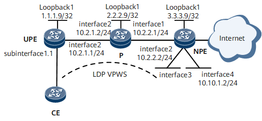
As shown in Figure 1, the LDP VPWS (access network) consists of the UPE, the P, and the NPE. The CE accesses the public network through the VPWS.
Global-VE1 and Global-VE2 are created on the NPE, with Global-VE1 serving as the L2VE to terminate the VPWS and Global-VE2 serving as the L3VE to access the public network.
OSPF is used to advertise the public network routes, with the OSPF process ID being 2.

Configuration Roadmap
The configuration roadmap is as follows:
Create L2VE and L3VE interfaces on the NPE. Bind them to the same VE-Group.
Configure a LDP VPWS, which involves:
Configure routing protocols for the devices (UPE, P, and NPE) on the access network to make the devices communicate, and enable MPLS.
Use the default tunnel policy and create LSPs to transmit service data.
Enable MPLS L2VPN and VCs on PEs and establish VCs.
Configure the access of the CE to the public network.
Data Preparation
To complete the configuration, you need the following data:
VE-Group number
IP address for Global-VE2
Procedure
- Create two GLOBAL-VE interfaces on the NPE, and bind them to the same VE-Group.
# Create Global-VE1 to terminate the MPLS L2VPN.
<HUAWEI> system-view
[~HUAWEI] sysname NPE
[*HUAWEI] commit
[~NPE] interface global-ve 1
[*NPE-Global-VE1] ve-group 1 l2-terminate
[*NPE-Global-VE1] quit
[*NPE] commit
# Create Global-VE2 to access the MPLS L3VPN.
[~NPE] interface global-ve 2
[*NPE-Global-VE2] ve-group 1 l3-access
[*NPE-Global-VE2] quit
[*NPE] commit
After the configuration is complete, run the display virtual-ethernet ve-group command. You can view the binding relationship between GLOBAL-VE interfaces and a VE-Group.
[~NPE] display virtual-ethernet ve-group Ve-groupID L2VE L3VE 1 Global-VE1 Global-VE2 Total 1, 1 printed - Run an IGP on the VPWS access network. OSPF is used in the example. The configuration details are not mentioned here.
Configure the addresses for the interfaces of the UPE, the P, and the NPE according to Figure 1. When configuring OSPF, advertise the 32-bit loopback interface addresses of the UPE, the P, and the NPE.
For more configurations, see "Configuration Files."
- Configure basic MPLS functions and LDP on the access network.
# Configure the UPE.
<HUAWEI> system-view
[~HUAWEI] sysname UPE
[*HUAWEI] commit
[~UPE] mpls lsr-id 1.1.1.9
[*UPE] mpls
[*UPE-mpls] quit
[*UPE] mpls ldp
[*UPE-mpls-ldp] quit
[*UPE] interface gigabitethernet 0/1/8
[*UPE-GigabitEthernet0/1/8] mpls
[*UPE-GigabitEthernet0/1/8] mpls ldp
[*UPE-GigabitEthernet0/1/8] quit
[*UPE] commit
# Configure the P.
<HUAWEI> system-view
[~HUAWEI] sysname P
[*HUAWEI] commit
[~P] mpls lsr-id 2.2.2.9
[*P] mpls
[*P-mpls] quit
[*P] mpls ldp
[*P-mpls-ldp] quit
[*P] interface gigabitethernet 0/1/0
[*P-GigabitEthernet0/1/0] mpls
[*P-GigabitEthernet0/1/0] mpls ldp
[*P-GigabitEthernet0/1/0] quit
[*P] interface gigabitethernet 0/1/8
[*P-GigabitEthernet0/1/8] mpls
[*P-GigabitEthernet0/1/8] mpls ldp
[*P-GigabitEthernet0/1/8] quit
[*P] commit
# Configure the NPE.
[~NPE] mpls lsr-id 3.3.3.9
[*NPE] mpls
[*NPE-mpls] quit
[*NPE] mpls ldp
[*NPE-mpls-ldp] quit
[*NPE] interface gigabitethernet 0/1/8
[*NPE-GigabitEthernet0/1/8] mpls
[*NPE-GigabitEthernet0/1/8] mpls ldp
[*NPE-GigabitEthernet0/1/8] quit
[*NPE] commit
- Establish a remote LDP session between the UPE and the NPE.
# Configure the UPE.
[~UPE] mpls ldp remote-peer 1
[*UPE-mpls-ldp-remote-1] remote-ip 3.3.3.9
[*UPE-mpls-ldp-remote-1] quit
[*UPE] commit
# Configure the NPE.
[~NPE] mpls ldp remote-peer 1
[*NPE-mpls-ldp-remote-1] remote-ip 1.1.1.9
[*NPE-mpls-ldp-remote-1] quit
[*NPE] commit
- Enable MPLS L2VPN on the UPE and NPE, and establish VCs.
# Configure the UPE.
[~UPE] mpls l2vpn
[*UPE-l2vpn] quit
[*UPE] interface gigabitethernet 0/1/0.1
[*UPE-GigabitEthernet0/1/0.1] shutdown
[*UPE-GigabitEthernet0/1/0.1] vlan-type dot1q 10
[*UPE-GigabitEthernet0/1/0.1] mpls l2vc 3.3.3.9 101
[*UPE-GigabitEthernet0/1/0.1] undo shutdown
[*UPE-GigabitEthernet0/1/0.1] quit
[*UPE] commit
# Configure the NPE.
[~NPE] mpls l2vpn
[*NPE-l2vpn] quit
[*NPE] interface global-ve 1.1
[*NPE-Global-VE1.1] vlan-type dot1q 1
[*NPE-Global-VE1.1] mpls l2vc 1.1.1.9 101
[*NPE-Global-VE1.1] quit
[*NPE] commit
- Verify the configuration.
Check the L2VPN connection on the PE. You can view that an L2VC in the Up state is set up.
Take the display on the NPE as an example.
[~NPE] display mpls l2vc
Total ldp vc : 1     1 up       0 down
 *Client Interface          : Global-VE1.1 is up
  Administrator PW          : no
  Session State             : up
  AC Status                 : up
  VC State                  : up
  Label state               : 0
  Token state               : 0
  VC ID                     : 101
  VC Type                   : vlan
  Destination               : 1.1.1.9
  local VC label            : 140288       remote VC label      : 140292
  control word              : disable
  remote control word       : disable
  forwarding entry          : exist
  local group ID            : 0
  remote group ID           : 0
  local AC OAM State        : up
  local PSN OAM State       : up
  local forwarding state    : forwarding
  local status code         : 0x0
  remote AC OAM state       : up
  remote PSN OAM state      : up
  remote forwarding state   : forwarding
  remote status code        : 0x0
  ignore standby state      : no
  BFD for PW                : unavailable
  VCCV State                : up
  manual fault              : not set
  active state              : active
  link state                : up
  local VC MTU              : 1500         remote VC MTU        : 1500
  local VCCV                : alert ttl lsp-ping bfd
  remote VCCV               : alert ttl lsp-ping bfd
  tunnel policy name        : --
  PW template name          : --
  primary or secondary      : primary
  load balance type         : flow
  Access-port               : false
  Switchover Flag           : false
  VC tunnel info            : 1 tunnels
    NO.0  TNL type          : ldp   , TNL ID : 0x0000000001004c4e42
  create time               : 0 days, 0 hours, 30 minutes, 18 seconds
  up time                   : 0 days, 0 hours, 0 minutes, 0 seconds
  last change time          : 0 days, 0 hours, 30 minutes, 18 seconds
  VC last up time           : 2012/07/24 12:31:31
  VC total up time          : 0 days, 2 hours, 12 minutes, 51 seconds
  CKey                      : 11
  NKey                      : 10
  PW redundancy mode        : frr
  AdminPw interface         : --
  AdminPw link state        : --
  Forward state             : send inactive, receive inactive
  Diffserv Mode             : uniform
  Service Class             : --
  Color                     : --
  DomainId                  : --
  Domain Name               : --
- Configure the access of the CE to the public network.
# Configure the NPE.
[~NPE] interface global-ve 2.1
[*NPE-Global-VE2.1] vlan-type dot1q 1
[*NPE-Global-VE2.1] ip address 10.10.1.2 24
[*NPE-Global-VE2.1] quit
[*NPE] ospf 2
[*NPE-ospf-2] area 0
[*NPE-ospf-2-area-0.0.0.0] network 10.10.1.0 0.0.0.255
[*NPE-ospf-2-area-0.0.0.0] quit
[*NPE-ospf-2] quit
[*NPE] commit
Configure the CE.
<HUAWEI> system-view
[~HUAWEI] sysname CE
[*HUAWEI] commit
[~CE] interface gigabitethernet0/1/0.1
[*CE-GigabitEthernet0/1/0.1] vlan-type dot1q 10
[*CE-GigabitEthernet0/1/0.1] ip address 10.10.1.1 24
[*CE-GigabitEthernet0/1/0.1] quit
[*CE] ospf 2
[*CE-ospf-2] area 0
[*CE-ospf-2-area-0.0.0.0] network 10.10.1.0 0.0.0.255
[*CE-ospf-2-area-0.0.0.0] quit
[*CE-ospf-2] quit
[*CE] commit
- Verify the configuration.
# The CE and NPE can ping each other successfully through Global-VE2.
Take the CE as example:
[~CE] ping 10.10.1.2
  PING 10.10.1.2: 56  data bytes, press CTRL_C to break
    Reply from 10.10.1.2: bytes=56 Sequence=1 ttl=255 time=31 ms
    Reply from 10.10.1.2: bytes=56 Sequence=2 ttl=255 time=10 ms
    Reply from 10.10.1.2: bytes=56 Sequence=3 ttl=255 time=5 ms
    Reply from 10.10.1.2: bytes=56 Sequence=4 ttl=255 time=2 ms
    Reply from 10.10.1.2: bytes=56 Sequence=5 ttl=255 time=28 ms
  --- 10.10.1.2 ping statistics ---
    5 packet(s) transmitted
    5 packet(s) received
    0.00% packet loss
round-trip min/avg/max = 2/15/31 ms
Configuration Files
Configuration file of the UPE
#
 sysname UPE
#
 mpls lsr-id 1.1.1.9
 mpls
#
 mpls l2vpn
#
mpls ldp
#
 mpls ldp remote-peer 1
 remote-ip 3.3.3.9
#
interface GigabitEthernet0/1/0
 undo shutdown
#
interface GigabitEthernet0/1/0.1
 vlan-type dot1q 10
 mpls l2vc 3.3.3.9 101
#
interface GigabitEthernet0/1/8
 undo shutdown
 ip address 10.2.1.1 255.255.255.0
 mpls
 mpls ldp
#
interface LoopBack1
 ip address 1.1.1.9 255.255.255.255
#
ospf 1
 area 0.0.0.0
  network 1.1.1.9 0.0.0.0
  network 10.2.1.0 0.0.0.255
#
return
Configuration file of the P
#
 sysname P
#
 mpls lsr-id 2.2.2.9
 mpls
#
mpls ldp
#
interface GigabitEthernet0/1/0
 undo shutdown
 ip address 10.2.2.1 255.255.255.0
 mpls
 mpls ldp
#
interface GigabitEthernet0/1/8
 undo shutdown
 ip address 10.2.1.2 255.255.255.0
 mpls
 mpls ldp
#
interface LoopBack1
 ip address 2.2.2.9 255.255.255.255
#
ospf 1
 area 0.0.0.0
  network 2.2.2.9 0.0.0.0
  network 10.2.1.0 0.0.0.255
  network 10.2.2.0 0.0.0.255
#
return
Configuration file of the NPE
#
 sysname NPE
#
 mpls lsr-id 3.3.3.9
 mpls
#
 mpls l2vpn
#
mpls ldp
#
 mpls ldp remote-peer 1
 remote-ip 1.1.1.9
#
interface Global-VE1
 ve-group 1 l2-terminate
#
#
interface Global-VE1.1
 vlan-type dot1q 1
 mpls l2vc 1.1.1.9 101
#
interface Global-VE2
 ve-group 1 l3-access
#
interface Global-VE2.1
 vlan-type dot1q 1
 ip address 10.10.1.2 255.255.255.0
#
interface GigabitEthernet0/1/8
 undo shutdown
 ip address 10.2.2.2 255.255.255.0
 mpls
 mpls ldp
#
interface LoopBack1
 ip address 3.3.3.9 255.255.255.255
#
ospf 1
 area 0.0.0.0
  network 3.3.3.9 0.0.0.0
  network 10.2.2.0 0.0.0.255
#
ospf 2
area 0.0.0.0
network 10.10.1.0 0.0.0.255
#
return
Configuration file of the CE
#
 sysname CE
#
interface GigabitEthernet0/1/0
 undo shutdown
#
interface GigabitEthernet0/1/0.1
 vlan-type dot1q 10
 ip address 10.10.1.1 255.255.255.0
#
ospf 2
 area 0.0.0.0
   network 10.10.1.0 0.0.0.255
#
return