Example for Configuring VPLS Accessing L3VPN (IP RAN Scenario)
The mixed VPN solution is a component of the IPTime MBB solution, which is developed by Huawei for constructing an IP MBH network.
Networking Requirements
In the mixed VPN solution, the RAN provides excellent FMC capability and adopts a simple and flexible networking scheme. The hierarchical network between CSGs and RSGs carries large-scale services.
CSGs are connected to form an access network. ASGs and RSGs are connected to form an aggregation network. All these devices can be flexibly deployed to meet 2G, 3G, and LTE service bearer requirements. The Figure 1 shows the mixed VPN solution.
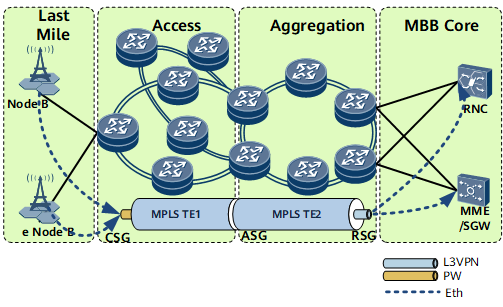
The integrated L2VPN accessing L3VPN solution allows Ethernet NodeBs to communicate with Radio Network Controllers (RNCs). It terminates the L2VPN and connects the L3VPN on an ASG by creating a Virtual Ethernet group (VE-Group). PW redundancy in master/slave mode is configured to protect PWs on the CSG. VRRP is configured between the ASGs to determine the role of master or backup. VRRP is also configured between RSGs to determine the role of master or backup. VPN FRR is configured to protect links on the L3VPN, providing reliable connections for services.

This example uses Virtual-Ethernet interface to configure L2VPN accessing L3VPN. As a VE interface is bound to only one board, when the board is faulty, services are interrupted. To improve service reliability, create two global virtual interfaces: Global-VE1 and Global-VE2. Global-VE1 is configured as an L2VE interface to terminate L2VPN services, and the Global-VE2 is configured as an L3VE interface to access an L3VPN network. Other configurations remain unchanged
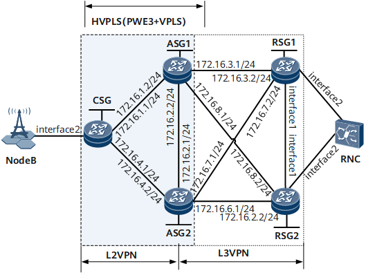
HVPLS or PWE3 can be used to construct the L2VPN. This example uses H-VPLS. Figure 2 shows a simplified single-ring network. The current versions are used for networking. The configurations on the CSG and ASG are mainly described.
Interfaces 1 and 2 in this example represent GE 0/1/0 and GE 0/1/3, respectively.
Device |
Interface |
Peer Device |
IP Address |
|---|---|---|---|
CSG |
GE0/1/1 |
ASG1 |
172.16.1.1/24 |
GE0/1/2 |
ASG2 |
172.16.4.1/24 |
|
GE0/1/3 |
NodeB |
- |
|
ASG1 |
GE0/1/0 |
ASG2 |
172.16.2.2/24 |
GE0/1/1 |
CSG |
172.16.1.2/24 |
|
GE0/1/3 |
RSG1 |
172.16.3.1/24 |
|
GE0/1/4 |
RSG2 |
172.16.8.1/24 |
|
ASG2 |
GE0/1/0 |
ASG1 |
172.16.2.1/24 |
GE0/1/2 |
CSG |
172.16.4.2/24 |
|
GE0/1/3 |
RSG2 |
172.16.6.1/24 |
|
GE0/1/4 |
RSG1 |
172.16.7.1/24 |
|
RSG1 |
GE0/1/0 |
RSG2 |
- |
GE0/1/1 |
ASG1 |
172.16.3.2/24 |
|
GE0/1/2 |
ASG2 |
172.16.7.2/24 |
|
GE0/1/3 |
RNC |
- |
|
RSG2 |
GE0/1/0 |
RSG1 |
- |
GE0/1/1 |
ASG2 |
172.16.6.2/24 |
|
GE0/1/2 |
ASG1 |
172.16.8.2/24 |
|
GE0/1/3 |
RNC |
- |
Configuration Roadmap
The configuration roadmap is as follows:
Configure IP addresses and routes.
Configure MPLS and public network tunnels.
- Configure TE tunnel between the CSG and ASGs.
- Configure LSPs between ASGs and RSGs.
Configure PW redundancy in master/slave mode.
- Configure H-VPLS (PWE3 accessing VPLS).
- Configure an mPW and a Spoke PW, and then associate the Spoke PW with the mPW.
- Configure BFD to monitor the mPW.
Configure an L3VPN.
- Configure the same VPN instance on ASGs and RSGs.
- Configure a VE-Group on ASGs and bind the VPN instance to the L3VE sub-interfaces.
- Establish MP-IBGP peer relationships between ASGs and RSGs.
- Import direct VPN routes to ASGs and RSGs.
- Configure VPN FRR.
Configure VRRP.
- Configure service VRRP and mVRRP on ASGs to determine a gateway for Ethernet NodeBs.
- Configure service VRRP on RSGs to determine their roles in the VRRP group.
Data Preparation
To complete the configuration, you need the following data:
Interface number, interface IP address, and OSPF process ID
LSR ID
L2VC's destination address, VC ID, and VC type
VSI name and VSI ID
BFD session name, local discriminator, and remote discriminator
VE-Group number
VRRP group number and priority
Procedure
- Assign an IP address to and configure a routing protocol on each interface.
- Configure a routing protocol on the CSG, ASG1, ASG2, RSG1, and RSG2 to make them routable. In this example, the Open Shortest Path First (OSPF) is used.
An access ring is used in this example. If multiple access rings are available, each access ring belongs to a different area. If IS-IS is used, each access ring belongs to a different IS-IS process, and a different NET is deployed for each access ring. If a small network is planned, Level-2 areas can be deployed on the entire network.
After the configuration is complete, run the display ip routing-table command on the CSG, ASGs, and RSGs. You can view the routes learned from each other. Note that when configuring OSPF, you need to advertise 32-bit loopback interface addresses (LSR IDs) of the CSG, ASGs, and RSGs.
The detailed configuration is not mentioned here. For details, please check Configuration Files.
- Configure a routing protocol on the CSG, ASG1, ASG2, RSG1, and RSG2 to make them routable. In this example, the Open Shortest Path First (OSPF) is used.
- Configure basic MPLS functions and public network tunnels.
- Configure explicit paths between the CSG and ASG1 and between the CSG and ASG2.
- Configure LSPs between ASGs and between ASGs and RSGs.
- To improve reliability, enable the Resource Reserved Protocol Graceful Restart (RSVP GR), LDP GR, and OSPF GR.
The detailed configuration is not mentioned here. For details, please check Configuration Files.
- Configure PW redundancy.
- Configure MPLS LDP remote sessions between the CSG and ASGs.
In this configuration example, TE tunnels are configured between the CSG and ASGs, and MPLS LDP is not required. PWE3, however, uses extended LDP signaling to distribute VPN labels. Therefore, MPLS LDP remote sessions have to be configured between the CSG and ASGs. An LDP LSP is configured to directly connect ASGs, and no LDP remote session needs to be configured between ASGs.
# Configure the CSG.
[~CSG] mpls ldp
[*CSG-mpls-ldp] quit
[*CSG] mpls ldp remote-peer 2.2.2.2
[*CSG-mpls-ldp-remote-2.2.2.2] remote-ip 2.2.2.2
[*CSG-mpls-ldp-remote-2.2.2.2] quit
[*CSG] mpls ldp remote-peer 3.3.3.3
[*CSG-mpls-ldp-remote-3.3.3.3] remote-ip 3.3.3.3
[*CSG-mpls-ldp-remote-3.3.3.3] quit
[*CSG] commit
# Configure the ASG1.
[~ASG1] mpls ldp
[*ASG1-mpls-ldp] quit
[*ASG1] mpls ldp remote-peer 1.1.1.1
[*ASG1-mpls-ldp-remote-1.1.1.1] remote-ip 1.1.1.1
[*ASG1-mpls-ldp-remote-1.1.1.1] quit
[*ASG1] commit
# Configure the ASG2.
[~ASG2] mpls ldp
[*ASG2-mpls-ldp] quit
[*ASG2] mpls ldp remote-peer 1.1.1.1
[*ASG2-mpls-ldp-remote-1.1.1.1] remote-ip 1.1.1.1
[*ASG2-mpls-ldp-remote-1.1.1.1] quit
[*ASG2] commit
- Configure H-VPLS.
- Configure PW redundancy in Master/Slave mode accessing VPLS on the CSG and ASGs to form an H-VPLS network. Configure PW redundancy in master/slave mode to protect the primary PW.
- Configure a Spoke PW between ASG1 and ASG2 so that AC links and PWs are not affected by each other's faults. This helps service traffic rapidly restore.
# Configure the CSG.
[~CSG] interface gigabitethernet 0/1/3
[*CSG-GigabitEthernet0/1/3] undo shutdown
[*CSG-GigabitEthernet0/1/3] quit
[*CSG] interface gigabitethernet 0/1/3.10
[*CSG-GigabitEthernet0/1/3.10] vlan-type dot1q 10
[*CSG-GigabitEthernet0/1/3.10] mpls l2vc 2.2.2.2 100 tunnel-policy policy1
[*CSG-GigabitEthernet0/1/3.10] mpls l2vc 3.3.3.3 200 tunnel-policy policy1 secondary
[*CSG-GigabitEthernet0/1/3.10] mpls l2vpn redundancy master
[*CSG-GigabitEthernet0/1/3.10] mpls l2vpn mac-withdraw disable
[*CSG-GigabitEthernet0/1/3.10] quit
[*CSG] commit
# Configure ASG1.
[~ASG1] vsi 1 static
[*ASG1-vsi-1] pwsignal ldp
[*ASG1-vsi-1-ldp] vsi-id 100
[*ASG1-vsi-1-ldp] peer 1.1.1.1 tnl-policy policy1 ignore-standby-state
[*ASG1-vsi-1-ldp] peer 3.3.3.3 negotiation-vc-id 8000 upe
[*ASG1-vsi-1-ldp] quit
[*ASG1-vsi-1] quit
[*ASG1] commit
# Configure ASG2.
[~ASG2] vsi 1 static
[*ASG2-vsi-1] pwsignal ldp
[*ASG2-vsi-1-ldp] vsi-id 200
[*ASG2-vsi-1-ldp] peer 1.1.1.1 tnl-policy policy1 ignore-standby-state
[*ASG2-vsi-1-ldp] peer 2.2.2.2 negotiation-vc-id 8000 upe
[*ASG2-vsi-1-ldp] quit
[*ASG2-vsi-1] quit
[*ASG2] commit
- Configure MPLS LDP remote sessions between the CSG and ASGs.
- Configure an L3VPN.
- Configure BFD to detect faults on public network links.
- Configure VRRP.
Configuration Files
Configuration file of the CSG
#
 sysname CSG
#
 bfd
#
 mpls lsr-id 1.1.1.1
 mpls
  mpls te
  mpls rsvp-te
  mpls rsvp-te hello
  mpls te cspf
#
 mpls l2vpn
#
explicit-path to_asg1
 next hop 172.16.1.2
 next hop 2.2.2.2
#
explicit-path to_asg2
 next hop 172.16.4.2
 next hop 3.3.3.3
#
mpls ldp
 graceful-restart
#
 mpls ldp remote-peer 2.2.2.2
 remote-ip 2.2.2.2
#
mpls ldp remote-peer 3.3.3.3
 remote-ip 3.3.3.3
#
interface GigabitEthernet0/1/1
 undo shutdown
 ip address 172.16.1.1 255.255.255.0
 mpls
 mpls te
 mpls rsvp-te
 mpls rsvp-te hello
#
interface GigabitEthernet0/1/2
 undo shutdown
 ip address 172.16.4.1 255.255.255.0
 mpls
 mpls te
 mpls rsvp-te
 mpls rsvp-te hello
#
interface GigabitEthernet0/1/3
 undo shutdown
#
interface GigabitEthernet0/1/3.10
 vlan-type dot1q 10
 mpls l2vc 2.2.2.2 100 tunnel-policy policy1
 mpls l2vc 3.3.3.3 200 tunnel-policy policy1 secondary
 mpls l2vpn redundancy master
#
interface LoopBack0
 ip address 1.1.1.1 255.255.255.255
#
interface Tunnel11
 ip address unnumbered interface LoopBack0
 tunnel-protocol mpls te
 destination 2.2.2.2
 mpls te tunnel-id 100
 mpls te path explicit-path path to_asg1
 mpls te reserved-for-binding
#
interface Tunnel12
 ip address unnumbered interface LoopBack0
 tunnel-protocol mpls te
 destination 3.3.3.3
 mpls te tunnel-id 200
 mpls te path explicit-path path to_asg2
 mpls te reserved-for-binding
#
ospf 100
 opaque-capability enable
 graceful-restart
 area 0.0.0.0
  network 1.1.1.1 0.0.0.0
  network 172.16.1.0 0.0.0.255
  network 172.16.4.0 0.0.0.255
  mpls-te enable
#
tunnel-policy policy1
 tunnel binding destination 2.2.2.2 te Tunnel11
 tunnel binding destination 3.3.3.3 te Tunnel12
#
bfd master bind pw interface GigabitEthernet0/1/3.10 remote-peer 2.2.2.2 pw-
ttl auto-calculate
 discriminator local 2
 discriminator remote 2
 commit
#
return
Configuration file of ASG1
#
 sysname ASG1
#
ip vpn-instance vpna
 ipv4-family
  route-distinguisher 1:1
  apply-label per-instance
  vpn frr
  vpn-target 1:1 export-extcommunity
  vpn-target 1:1 import-extcommunity
#
 bfd
#
 mpls lsr-id 2.2.2.2
 mpls
  mpls te
  mpls rsvp-te
  mpls rsvp-te hello
  mpls te cspf
#
 mpls l2vpn
#
vsi 1 static
 pwsignal ldp
  vsi-id 100
  peer 1.1.1.1 tnl-policy policy1 ignore-standby-state
  peer 3.3.3.3 negotiation-vc-id 8000 upe
#
 explicit-path to_csg
  next hop 172.16.1.1
  next hop 1.1.1.1
#
mpls ldp
 graceful-restart
#
 mpls ldp remote-peer 1.1.1.1
 remote-ip 1.1.1.1
#
interface GigabitEthernet0/1/0
 undo shutdown
 ip address 172.16.2.2 255.255.255.0
 vrrp vrid 20 virtual-ip 172.16.2.3
 admin-vrrp vrid 20 ignore-if-down
 vrrp vrid 20 priority 150
 mpls
 mpls ldp
#
interface GigabitEthernet0/1/1
 undo shutdown
 ip address 172.16.1.2 255.255.255.0
 mpls
 mpls te
 mpls rsvp-te
 mpls rsvp-te hello
#
interface GigabitEthernet0/1/3
 undo shutdown
 ip address 172.16.3.1 255.255.255.0
 mpls
 mpls ldp
#
interface GigabitEthernet0/1/4
 undo shutdown
 ip address 172.16.8.1 255.255.255.0
 mpls
 mpls ldp
#
interface Virtual-Ethernet0/1/0
 ve-group 10 l2-terminate
#
interface Virtual-Ethernet0/1/0.1
 vlan-type dot1q 10
 l2 binding vsi 1
#
interface Virtual-Ethernet0/1/1
 ve-group 10 l3-access
#
interface Virtual-Ethernet0/1/1.1
 vlan-type dot1q 10
 ip binding vpn-instance vpna
 ip address 10.0.0.2 255.255.255.0
 direct-route track pw-state degrade-cost 30
 vrrp vrid 10 virtual-ip 10.0.0.3
 vrrp vrid 10 track admin-vrrp interface GigabitEthernet0/1/0 vrid 20
#
interface LoopBack0
 ip address 2.2.2.2 255.255.255.255
#
interface Tunnel11
 ip address unnumbered interface LoopBack0
 tunnel-protocol mpls te
 destination 1.1.1.1
 mpls te tunnel-id 100
 mpls te record-route
 mpls te signal-protocol rsvp-te
 mpls te path explicit-path to_csg
 mpls te backup hot-standby wtr 15
 mpls te reserved-for-binding
#
bgp 100
 graceful-restart
 peer 3.3.3.3 as-number 100
 peer 3.3.3.3 connect-interface LoopBack0
 peer 4.4.4.4 as-number 100
 peer 4.4.4.4 connect-interface LoopBack0
 peer 5.5.5.5 as-number 100
 peer 5.5.5.5 connect-interface LoopBack0
 #
 ipv4-family unicast
  undo synchronization
  peer 3.3.3.3 enable
  peer 4.4.4.4 enable
  peer 5.5.5.5 enable
 #
 ipv4-family vpnv4
  policy vpn-target
  peer 3.3.3.3 enable
  peer 4.4.4.4 enable
  peer 5.5.5.5 enable
 #
 ipv4-family vpn-instance vpna
  import-route direct
#
ospf 100
 opaque-capability enable
 graceful-restart
 area 0.0.0.0
  network 2.2.2.2 0.0.0.0
  network 172.16.1.0 0.0.0.255
  network 172.16.3.0 0.0.0.255
  network 172.16.2.0 0.0.0.255
  network 172.16.8.0 0.0.0.255
  mpls-te enable
#
tunnel-policy policy1
 tunnel binding destination 1.1.1.1 te Tunnel11
#
bfd master bind pw vsi 1 peer 1.1.1.1 remote-peer 1.1.1.1 pw-ttl auto-calculate
 discriminator local 2
 discriminator remote 2
 commit
#
bfd spoke bind pw vsi 1 peer 3.3.3.3 vc-id 8000
 discriminator local 5
 discriminator remote 5
 commit
#
return
Configuration file of ASG2
#
 sysname ASG2
#
ip vpn-instance vpna
 ipv4-family
  route-distinguisher 1:1
  apply-label per-instance
  vpn frr
  vpn-target 1:1 export-extcommunity
  vpn-target 1:1 import-extcommunity
#
 bfd
#
 mpls lsr-id 3.3.3.3
 mpls
  mpls te
  mpls rsvp-te
  mpls rsvp-te hello
  mpls te cspf
#
 mpls l2vpn
#
vsi 1 static
 pwsignal ldp
  vsi-id 200
  peer 1.1.1.1 tnl-policy policy1 ignore-standby-state
  peer 2.2.2.2 negotiation-vc-id 8000 upe
#
 explicit-path to_csg
  next hop 172.16.4.1
  next hop 1.1.1.1
#
mpls ldp
 graceful-restart
#
 mpls ldp remote-peer 1.1.1.1
 remote-ip 1.1.1.1
#
interface GigabitEthernet0/1/0
 undo shutdown
 ip address 172.16.2.1 255.255.255.0
 vrrp vrid 20 virtual-ip 172.16.2.3
 admin-vrrp vrid 20 ignore-if-down
 mpls
 mpls ldp
#
interface GigabitEthernet0/1/2
 undo shutdown
 ip address 172.16.4.2 255.255.255.0
 mpls
 mpls te
 mpls rsvp-te
 mpls rsvp-te hello
#
interface GigabitEthernet0/1/3
 undo shutdown
 ip address 172.16.6.1 255.255.255.0
 mpls
 mpls ldp
#
interface GigabitEthernet0/1/4
 undo shutdown
 ip address 172.16.7.1 255.255.255.0
 mpls
 mpls ldp
#
interface Virtual-Ethernet0/1/0
 ve-group 10 l2-terminate
#
interface Virtual-Ethernet0/1/0.1
 vlan-type dot1q 10
 l2 binding vsi 1
#
interface Virtual-Ethernet0/1/1
 ve-group 10 l3-access
#
interface Virtual-Ethernet0/1/1.1
 vlan-type dot1q 10
 ip binding vpn-instance vpna
 ip address 10.0.0.4 255.255.255.0
 vrrp vrid 10 virtual-ip 10.0.0.3
 vrrp vrid 10 track admin-vrrp interface GigabitEthernet0/1/0 vrid 20
#
interface LoopBack0
 ip address 3.3.3.3 255.255.255.255
#
interface Tunnel12
 ip address unnumbered interface LoopBack0
 tunnel-protocol mpls te
 destination 1.1.1.1
 mpls te tunnel-id 200
 mpls te record-route
 mpls te signal-protocol rsvp-te
 mpls te path explicit-path to_csg
 mpls te backup hot-standby wtr 15
 mpls te reserved-for-binding
#
bgp 100
 graceful-restart
 peer 2.2.2.2 as-number 100
 peer 2.2.2.2 connect-interface LoopBack0
 peer 4.4.4.4 as-number 100
 peer 4.4.4.4 connect-interface LoopBack0
 peer 5.5.5.5 as-number 100
 peer 5.5.5.5 connect-interface LoopBack0
 #
 ipv4-family unicast
  undo synchronization
  peer 2.2.2.2 enable
  peer 4.4.4.4 enable
  peer 5.5.5.5 enable
 #
 ipv4-family vpnv4
  policy vpn-target
  peer 2.2.2.2 enable
  peer 4.4.4.4 enable
  peer 5.5.5.5 enable
 #
 ipv4-family vpn-instance vpna
  import-route direct
#
ospf 100
 opaque-capability enable
 graceful-restart
 area 0.0.0.0
  network 3.3.3.3 0.0.0.0
  network 172.16.2.0 0.0.0.255
  network 172.16.7.0 0.0.0.255
  network 172.16.4.0 0.0.0.255
  network 172.16.6.0 0.0.0.255
  mpls-te enable
#
tunnel-policy policy1
 tunnel binding destination 1.1.1.1 te Tunnel12
#
bfd spoke bind pw vsi 1 peer 2.2.2.2 vc-id 8000
 discriminator local 5
 discriminator remote 5
 commit
#
return
Configuration file of RSG1
#
 sysname RSG1
#
 vlan batch 10
#
ip vpn-instance vpna
 ipv4-family
  route-distinguisher 1:1
  apply-label per-instance
  vpn frr
  vpn-target 1:1 export-extcommunity
  vpn-target 1:1 import-extcommunity
#
 mpls lsr-id 4.4.4.4
 mpls
#
 mpls l2vpn
#
mpls ldp
 graceful-restart
#
interface Vlanif10
 ip binding vpn-instance vpna
 ip address 10.0.1.1 255.255.255.0
 vrrp vrid 1 virtual-ip 10.0.1.3
 vrrp vrid 1 priority 150
#
interface GigabitEthernet0/1/0
 portswitch
 undo shutdown
 port link-type trunk
 port trunk allow-pass vlan 10
#
interface GigabitEthernet0/1/1
 undo shutdown
 ip address 172.16.3.2 255.255.255.0
 mpls
 mpls ldp
#
interface GigabitEthernet0/1/2
 undo shutdown
 ip address 172.16.7.2 255.255.255.0
 mpls
 mpls ldp
#
interface GigabitEthernet0/1/3
 portswitch
 undo shutdown
 port link-type trunk
 port trunk allow-pass vlan 10
#
interface LoopBack0
 ip address 4.4.4.4 255.255.255.255
#
bgp 100
 graceful-restart
 peer 2.2.2.2 as-number 100
 peer 2.2.2.2 connect-interface LoopBack0
 peer 3.3.3.3 as-number 100
 peer 3.3.3.3 connect-interface LoopBack0
 peer 5.5.5.5 as-number 100
 peer 5.5.5.5 connect-interface LoopBack0
 #
 ipv4-family unicast
  undo synchronization
  peer 2.2.2.2 enable
  peer 3.3.3.3 enable
  peer 5.5.5.5 enable
 #
 ipv4-family vpnv4
  policy vpn-target
  peer 2.2.2.2 enable
  peer 3.3.3.3 enable
  peer 5.5.5.5 enable
 #
 ipv4-family vpn-instance vpna
  import-route direct
#
ospf 100
 opaque-capability enable
 graceful-restart
 area 0.0.0.0
  network 4.4.4.4 0.0.0.0
  network 172.16.3.0 0.0.0.255
  network 172.16.7.0 0.0.0.255
  mpls-te enable
#
return
Configuration file of RSG2
#
 sysname RSG2
#
 vlan batch 10
#
ip vpn-instance vpna
 ipv4-family
  route-distinguisher 1:1
  apply-label per-instance
  vpn frr
  vpn-target 11 export-extcommunity
  vpn-target 11 import-extcommunity
#
 mpls lsr-id 5.5.5.5
 mpls
#
 mpls l2vpn
#
mpls ldp
 graceful-restart
#
interface Vlanif10
 ip binding vpn-instance vpna
 ip address 10.0.1.2 255.255.255.0
 vrrp vrid 1 virtual-ip 10.0.1.3
#
interface GigabitEthernet0/1/0
 portswitch
 undo shutdown
 port link-type trunk
 port trunk allow-pass vlan 10
#
interface GigabitEthernet0/1/1
 undo shutdown
 ip address 172.16.6.2 255.255.255.0
 mpls
 mpls ldp
#
interface GigabitEthernet0/1/2
 undo shutdown
 ip address 172.16.8.2 255.255.255.0
 mpls
 mpls ldp
#
interface GigabitEthernet0/1/3
 portswitch
 undo shutdown
 port link-type trunk
 port trunk allow-pass vlan 10
#
interface LoopBack0
 ip address 5.5.5.5 255.255.255.255
#
bgp 100
 graceful-restart
 peer 2.2.2.2 as-number 100
 peer 2.2.2.2 connect-interface LoopBack0
 peer 3.3.3.3 as-number 100
 peer 3.3.3.3 connect-interface LoopBack0
 peer 4.4.4.4 as-number 100
 peer 4.4.4.4 connect-interface LoopBack0
 #
 ipv4-family unicast
  undo synchronization
  peer 2.2.2.2 enable
  peer 3.3.3.3 enable
  peer 4.4.4.4 enable
 #
 ipv4-family vpnv4
  policy vpn-target
  peer 2.2.2.2 enable
  peer 3.3.3.3 enable
  peer 4.4.4.4 enable
 #
 ipv4-family vpn-instance vpna
  import-route direct
#
ospf 100
 opaque-capability enable
 graceful-restart
 area 0.0.0.0
  network 5.5.5.5 0.0.0.0
  network 172.16.8.0 0.0.0.255
  network 172.16.6.0 0.0.0.255
  mpls-te enable
#
return