Example for Configuring IGMP Snooping for a VSI
This section provides an example for configuring IGMP snooping for a VSI in typical VPLS networking.
Networking Requirements
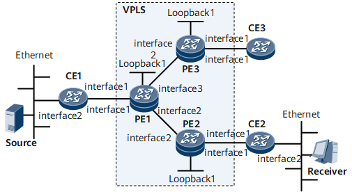
On the network shown in Figure 1, PE1 serves as the superstratum provider edge (SPE) device, and PE2 and PE3 serve as the UPE devices on the VPLS network. The multicast data is broadcast to all PWs if IGMP snooping is not configured in the VSI on PE1. This wastes network resources.
After IGMP snooping is configured for the VSI, however, the multicast data is sent to only access devices of multicast receivers, reducing network resource consumption.
On a network with a stable topology, configure GE 0/1/0 on PE1 as a static router port and the PW on PE2 as a static router port in the VSI. In this manner, receivers can steadily receive multicast data.
The aging time of router ports can be set based on the network stability condition so that multicast entries are updated upon network changes. The aging time of multicast entries is set to 100s in a VSI.
IGMP snooping proxy must be enabled in VSIs to relieve the packet processing pressure on Layer 3 devices.

Interfaces 1 through 3 in this example represent GE 0/1/0, GE 0/1/8, and GE 0/1/16, respectively.
Device |
Interface |
IP Address |
|---|---|---|
PE1 |
GE0/1/8 |
10.1.1.1/30 |
GE0/1/16 |
10.1.2.1/30 |
|
Loopback1 |
1.1.1.1/32 |
|
PE2 |
GE0/1/8 |
10.1.1.2/30 |
Loopback1 |
2.2.2.2/32 |
|
PE3 |
GE0/1/8 |
10.1.2.2/30 |
Loopback1 |
3.3.3.3/32 |
|
CE1 |
GE0/1/0 |
10.1.3.1/30 |
CE2 |
GE0/1/0 |
10.1.4.1/30 |
CE3 |
GE0/1/0 |
10.1.5.1/30 |
Configuration Roadmap
The configuration roadmap is as follows:
Configure basic VPLS functions.
Enable IGMP snooping both globally and in a specified VSI.
Set the timer for deleting multicast forwarding entries in the VSI.
Data Preparation
To complete the configuration, you need the following data:
ID of the VSI and VSI name
Timer for deleting multicast forwarding entries
Procedure
- Enable Open Shortest Path First (OSPF) to advertise the network segment of each router's interface and ID of the Label Switch Router (LSR).
For configuration details, see the OSPF Configuration.
- Configure basic MPLS functions and the Label Distribution Protocol (LDP).
# Configure PE1.
<PE1> system-view
[~PE1] mpls lsr-id 1.1.1.1
[*PE1] mpls
[*PE1-mpls] quit
[*PE1] mpls ldp
[*PE1-mpls-ldp] quit
[*PE1] interface gigabitethernet 0/1/8
[*PE1-GigabitEthernet0/1/8] mpls
[*PE1-GigabitEthernet0/1/8] mpls ldp
[*PE1-GigabitEthernet0/1/8]quit
[*PE1] interface gigabitethernet 0/1/16
[*PE1-GigabitEthernet0/1/16] mpls
[*PE1-GigabitEthernet0/1/16] mpls ldp
[*PE1-GigabitEthernet0/1/16] commit
[~PE1-GigabitEthernet0/1/16] quit
# Configure PE2.
<PE2> system-view
[~PE2] mpls lsr-id 2.2.2.2
[*PE2] mpls
[*PE2-mpls] quit
[*PE2] mpls ldp
[*PE2-mpls-ldp] quit
[*PE2] interface gigabitethernet 0/1/8
[*PE2-GigabitEthernet0/1/8] mpls
[*PE2-GigabitEthernet0/1/8] mpls ldp
[*PE2-GigabitEthernet0/1/8] commit
[~PE2-GigabitEthernet0/1/8] quit
# Configure PE3.
<PE3> system-view
[~PE3] mpls lsr-id 3.3.3.3
[*PE3] mpls
[*PE3-mpls] quit
[*PE3] mpls ldp
[*PE3-mpls-ldp] quit
[*PE3] interface gigabitethernet 0/1/8
[*PE3-GigabitEthernet0/1/8] mpls
[*PE3-GigabitEthernet0/1/8] mpls ldp
[*PE3-GigabitEthernet0/1/8] commit
[~PE3-GigabitEthernet0/1/8] quit
- Enable MPLS L2VPN and configure a VSI.
# Configure PE1.
[~PE1] mpls l2vpn
[*PE1-l2vpn] quit
[*PE1] vsi v123 static
[*PE1-vsi-v123] pwsignal ldp
[*PE1-vsi-v123-ldp] vsi-id 123
[*PE1-vsi-v123-ldp] peer 2.2.2.2 upe
[*PE1-vsi-v123-ldp] peer 3.3.3.3 upe
[*PE1-vsi-v123-ldp] commit
[~PE1-vsi-v123-ldp] quit
[~PE1-vsi-v123] quit
# Configure PE2.
[~PE2] mpls l2vpn
[*PE2-l2vpn] quit
[*PE2] vsi v123 static
[*PE2-vsi-v123] pwsignal ldp
[*PE2-vsi-v123-ldp] vsi-id 123
[*PE2-vsi-v123-ldp] peer 1.1.1.1
[*PE2-vsi-v123-ldp] commit
[~PE2-vsi-v123-ldp] quit
[~PE2-vsi-v123] quit
# Configure PE3.
[~PE3] mpls l2vpn
[*PE3-l2vpn] quit
[*PE3] vsi v123 static
[*PE3-vsi-v123] pwsignal ldp
[*PE3-vsi-v123-ldp] vsi-id 123
[*PE3-vsi-v123-ldp] peer 1.1.1.1
[*PE3-vsi-v123-ldp] commit
[~PE3-vsi-v123-ldp] quit
[~PE3-vsi-v123] quit
- Bind the VSI on the PE devices to interfaces.
# Configure PE1.
[~PE1] vlan 10
[*PE1-vlan10] quit
[*PE1] interface gigabitethernet 0/1/0
[*PE1-GigabitEthernet0/1/0] portswitch
[*PE1-GigabitEthernet0/1/0] port link-type access
[*PE1-GigabitEthernet0/1/0] port default vlan 10
[*PE1-GigabitEthernet0/1/0] undo shutdown
[*PE1-GigabitEthernet0/1/0] quit
[*PE1] interface vlanif 10
[*PE1-Vlanif10] l2 binding vsi v123
[*PE1-Vlanif10] commit
[~PE1-Vlanif10] quit
The configurations of PE2 and PE3 are similar to those of PE1 and are not mentioned here.
- Enable IGMP snooping globally and for the VSI on the PE devices.
# Configure PE1.
[~PE1] igmp-snooping enable
[*PE1] vsi v123
[*PE1-vsi-v123] igmp-snooping enable
[*PE1-vsi-v123] igmp-snooping version 3
[*PE1-vsi-v123] commit
[~PE1-vsi-v123] quit
The configurations of PE2 and PE3 are similar to those of PE1 and are not mentioned here.
- Configure GE 0/1/0 on PE1 as a static router port in VLAN 10 and the PW on PE2 as a static router port.
# Configure PE1.
[~PE1] interface gigabitethernet 0/1/0
[*PE1-GigabitEthernet0/1/0] igmp-snooping static-router-port vlan 10
[*PE1-GigabitEthernet0/1/0] commit
[~PE1-GigabitEthernet0/1/0] quit
# Configure PE2.
[~PE2] vsi v123
[*PE2-vsi-v123] igmp-snooping static-router-port remote-peer 1.1.1.1
[*PE2-vsi-v123] commit
[~PE2-vsi-v123] quit
- Set the timer for deleting multicast forwarding entries in the VSI to 100s.
# Configure PE1.
[~PE1] vsi v123
[*PE1-vsi-v123] l2-multicast source-lifetime 100
[*PE1-vsi-v123] igmp-snooping proxy
[*PE1-vsi-v123] commit
[~PE1-vsi-v123] quit
- Verify the configuration.
# After completing the configurations, run the display igmp-snooping router-port vsi command on PE1 to view information about the static router port.
[~PE1] display igmp-snooping router-port vsi v123
Port Name                       UpTime        Expires       Flags
 ---------------------------------------------------------------------
 VSI v123, 1 router-port(s)
 GE0/1/0(VID:10)                 00:21:05      --            STATIC
If the command output contains STATIC, GE 0/1/0 has been configured as a static router port in the VSI.
# After completing the configurations, run the display igmp-snooping router-port vsi command on PE2 to view information about the static router port.
[~PE2] display igmp-snooping router-port vsi v123
 Port Name                       UpTime        Expires       Flags
 ---------------------------------------------------------------------
 VSI v123, 1 router-port(s)
 PW(1.1.1.1/123)                 00:05:16      --            STATIC
If the command output contains STATIC, PW (1.1.1.1/123) has been configured as a static router port.
Configuration Files
PE1 configuration file
#
 sysname PE1
#
 vlan batch 10
#
igmp-snooping enable
#
 mpls lsr-id 1.1.1.1
 mpls
#
mpls l2vpn
#
vsi v123 static
 pwsignal ldp
  vsi-id 123
  peer 2.2.2.2 upe
  peer 3.3.3.3 upe
igmp-snooping enable
igmp-snooping proxy
igmp-snooping version 3
l2-multicast source-lifetime 100
#
mpls ldp
#
interface Vlanif10
 l2 binding vsi v123
#
interface GigabitEthernet0/1/0
 undo shutdown
 portswitch
 port link-type access
 port default vlan 10
igmp-snooping static-router-port vlan 10
#
interface GigabitEthernet0/1/8
undo shutdown
ip address 10.1.1.1 255.255.255.252
 mpls
 mpls ldp
#
interface GigabitEthernet0/1/16
undo shutdown
 ip address 10.1.2.1 255.255.255.252
 mpls
 mpls ldp
#
interface LoopBack1
 ip address 1.1.1.1 255.255.255.255
#
ospf 1
 area 0.0.0.0
  network 1.1.1.1 0.0.0.0
  network 10.1.1.0 0.0.0.3
  network 10.1.2.0 0.0.0.3
#
return
PE2 configuration file
#
 sysname PE2
#
 vlan batch 10
#
igmp-snooping enable
#
 mpls lsr-id 2.2.2.2
 mpls
#
mpls l2vpn
#
vsi v123 static
 pwsignal ldp
  vsi-id 123
  peer 1.1.1.1
igmp-snooping enable
igmp-snooping version 3
igmp-snooping static-router-port remote-peer 1.1.1.1
#
mpls ldp
#
interface Vlanif10
 l2 binding vsi v123
#
interface GigabitEthernet0/1/0
 undo shutdown
 portswitch
 port link-type access
 port default vlan 10
#
interface GigabitEthernet0/1/8
undo shutdown
ip address 10.1.1.2 255.255.255.252
 mpls
 mpls ldp
#
interface LoopBack1
 ip address 2.2.2.2 255.255.255.255
#
ospf 1
 area 0.0.0.0
  network 2.2.2.2 0.0.0.0
  network 10.1.1.0 0.0.0.3
#
return
PE3 configuration file
#
 sysname PE3
#
 vlan batch 10
#
igmp-snooping enable
#
 mpls lsr-id 3.3.3.3
 mpls
#
mpls l2vpn
#
vsi v123 static
 pwsignal ldp
  vsi-id 123
  peer 1.1.1.1
igmp-snooping enable
igmp-snooping version 3
#
mpls ldp
#
interface Vlanif10
 l2 binding vsi v123
#
interface GigabitEthernet0/1/0
 undo shutdown
 portswitch
 port link-type access
 port default vlan 10
#
interface GigabitEthernet0/1/8
undo shutdown
 ip address 10.1.2.2 255.255.255.252
 mpls
 mpls ldp
#
interface LoopBack1
 ip address 3.3.3.3 255.255.255.255
#
ospf 1
 area 0.0.0.0
  network 3.3.3.3 0.0.0.0
  network 10.1.2.0 0.0.0.3
#
return
CE1 configuration file
#
 sysname CE1
#
 multicast routing-enable
#
interface GigabitEthernet 0/1/0
 undo shutdown
 ip address 10.1.3.1 255.255.255.252
 pim sm
 igmp enable
#
ospf 1
area 0.0.0.0
network 10.1.1.0 0.0.0.3
#
return