Example for Configuring Multicast Functions in Daisy-Chain Networking
This section provides an example for configuring multicast functions in daisy-chain networking. Deploying multicast services in daisy-chain networking prevents the transmission of duplicate multicast data on a MAN ring, thereby saving network bandwidth.
Networking Requirements
Figure 1 shows a typical multicast networking. SR is a master service termination point and BSR is a backup SR. Protocol Independent Multicast - Sparse Mode (PIM-SM) is configured on the network side of SR to enable SR to receive multicast data and IGMP is configured on the user side of SR to manage multicast group members. On the MAN, UPEs and NPEs transparently transmit user requests and multicast traffic over PWs. NPE1 needs to set up a PW with each UPE. (NPE2 backs up NPE1.)
After multicast traffic reaches NPEs, it must be replicated on the leaf network. If devices attached to each UPE require this multicast traffic, NPE1 must replicate a copy of multicast traffic for each PW connecting a UPE.
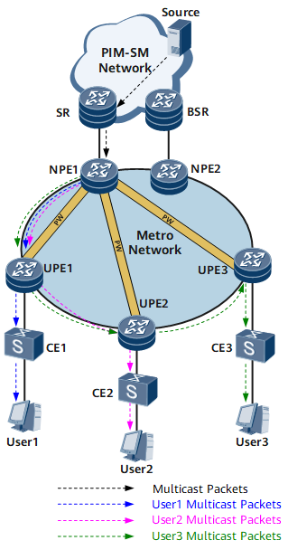
- The traffic forwarding path corresponding to the PW from NPE1 to UPE1 is NPE1 -> UPE1.
- The traffic forwarding path corresponding to the PW from NPE1 to UPE2 is NPE1 -> UPE1 -> UPE2.
- The traffic forwarding path corresponding to the PW from NPE1 to UPE3 is NPE1 -> UPE1 -> UPE2 -> UPE3.
The daisy-chain networking can solve this problem. Figure 2 shows the daisy-chain networking.
In this networking, a UPE sets up a PW with only an adjacent UPE or NPE. As a result, on the entire MAN ring, a chain composed of VPLS PWs is formed and only one copy of data is transmitted along the chain. Such a chain is called a daisy chain. On a daisy chain, an NPE no long needs to set up PWs with all UPEs, preventing duplicate multicast traffic transmission.

- Unicast services are transmitted over point-to-point connections and therefore will not be transmitted repeatedly over a PW.
- The daisy-chain networking makes configuration and reliability protection more complex.
Interfaces 1 through 3 in this example represent GE 0/1/0, GE 0/1/1, and GE 0/1/2, respectively.
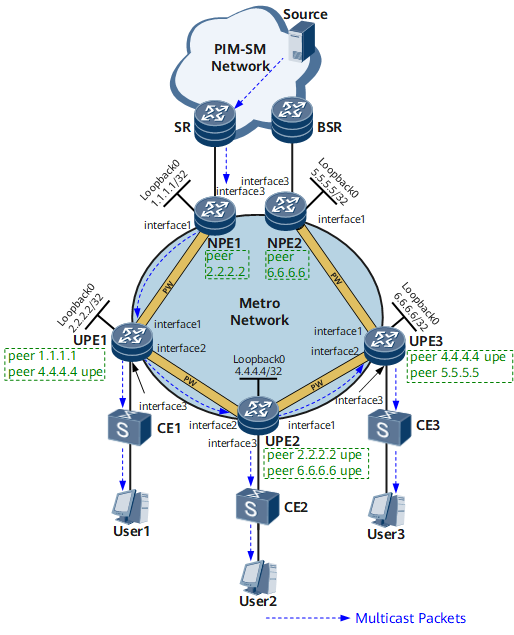
Device |
Interface |
IP Address |
NPE1 |
GE 0/1/0 |
10.11.11.1/30 |
NPE2 |
GE 0/1/0 |
10.11.14.2/30 |
UPE1 |
GE 0/1/0 |
10.11.11.2/30 |
UPE1 |
GE 0/1/1 |
10.11.12.1/30 |
UPE2 |
GE 0/1/0 |
10.11.13.1/30 |
UPE2 |
GE 0/1/1 |
10.11.12.2/30 |
UPE3 |
GE 0/1/0 |
10.11.14.1/30 |
UPE3 |
GE 0/1/1 |
10.11.13.2/30 |
Configuration Roadmap
The configuration roadmap is as follows:
Configure basic MPLS functions and L2VPN functions on each device to ensure that multicast services run properly on the L2VPN.
Create the VSI btv on each device; create a PW between an NPE and its adjacent UPE and a Spoke PW between every two UPEs so that virtual tunnels exist between adjacent devices.
Configure IGMP snooping and IGMP Snooping proxy for the VSI to manage the forwarding of multicast data packets. An IGMP Snooping Proxy substitutes for both upstream and downstream devices to send multicast protocol packets, which implements on-demand multicast data forwarding on the Layer 2 VPLS network and saves network bandwidth.
Add the sub-interface bound to the VSI on each device to a multicast group statically so that users attached to each device can steadily receive multicast data for the multicast groups, avoiding network attacks.
Data Preparation
To complete the configuration, you need the following data:
IP addresses of the interfaces and loopback address of each device (for details, see Figure 2)
IP routing protocol (IS-IS is used in this example and the process ID is 1)
MPLS Label Switch Router (LSR) ID of each device (consistent with loopback address of each device)
VSI name (btv is used in this example) used when setting up a PW between every two adjacent devices
Sub-interface bound to the VSI on each UPE and VLAN to which users belong (GE0/1/2.1 and VLAN 10 are used in this example)
Address of the multicast group to which users attached to UPE1, UPE2, and UPE3 are to be statically added (225.0.0.1 is used in this example)
Procedure
- Configure interface IP addresses, loopback addresses, and IS-IS on all NPEs and UPEs.
# Configure NPE1.
<HUAWEI> system-view
[~HUAWEI] sysname NPE1
[*HUAWEI] commit
[~NPE1] interface LoopBack 0
[*NPE1-LoopBack0] ip address 1.1.1.1 32
[*NPE1-LoopBack0] quit
[*NPE1] interface gigabitethernet 0/1/0
[*NPE1-gigabitethernet0/1/0] undo shutdown
[*NPE1-GigabitEthernet0/1/0] ip address 10.11.11.1 30
[*NPE1-GigabitEthernet0/1/0] quit
[*NPE1] isis 1
[*NPE1-isis-1] is-level level-1
[*NPE1-isis-1] network-entity 49.0010.0100.1001.00
[*NPE1-isis-1] quit
[*NPE1] interface gigabitethernet 0/1/0
[*NPE1-GigabitEthernet0/1/0] isis enable
[*NPE1-GigabitEthernet0/1/0] quit
[*NPE1] interface LoopBack 0
[*NPE1-LoopBack0] isis enable
[*NPE1-LoopBack0] commit
[~NPE1-LoopBack0] quit
# Configure NPE2.
<HUAWEI> system-view
[~HUAWEI] sysname NPE2
[*HUAWEI] commit
[~NPE2] interface LoopBack 0
[*NPE2-LoopBack0] ip address 5.5.5.5 32
[*NPE2-LoopBack0] quit
[*NPE2] interface gigabitethernet 0/1/0
[*NPE2-GigabitEthernet0/1/0] undo shutdown
[*NPE2-GigabitEthernet0/1/0] ip address 10.11.14.2 30
[*NPE2-GigabitEthernet0/1/0] quit
[*NPE2] isis 1
[*NPE2-isis-1] is-level level-1
[*NPE2-isis-1] network-entity 49.0050.0500.5005.00
[*NPE2-isis-1] quit
[*NPE2] interface gigabitethernet 0/1/0
[*NPE2-GigabitEthernet0/1/0] isis enable
[*NPE2-GigabitEthernet0/1/0] quit
[*NPE2] interface LoopBack 0
[*NPE2-LoopBack0] isis enable
[*NPE2-LoopBack0] commit
[~NPE2-LoopBack0] quit
# Configure UPE1.
<HUAWEI> system-view
[~HUAWEI] sysname UPE1
[*HUAWEI] commit
[~UPE1] interface LoopBack 0
[*UPE1-LoopBack0] ip address 2.2.2.2 32
[*UPE1-LoopBack0] quit
[*UPE1] interface gigabitethernet 0/1/0
[*UPE1-GigabitEthernet0/1/0] undo shutdown
[*UPE1-GigabitEthernet0/1/0] ip address 10.11.11.2 30
[*UPE1-GigabitEthernet0/1/0] quit
[*UPE1] interface gigabitethernet 0/1/1
[*UPE1-GigabitEthernet0/1/1] undo shutdown
[*UPE1-GigabitEthernet0/1/1] ip address 10.11.12.1 30
[*UPE1-GigabitEthernet0/1/1] quit
[*UPE1] isis 1
[*UPE1-isis-1] is-level level-1
[*UPE1-isis-1] network-entity 49.0020.0200.2002.00
[*UPE1-isis-1] quit
[*UPE1] interface LoopBack 0
[*UPE1-LoopBack0] isis enable
[*UPE1-LoopBack0] quit
[*UPE1] interface gigabitethernet 0/1/0
[*UPE1-GigabitEthernet0/1/0] isis enable
[*UPE1-GigabitEthernet0/1/0] quit
[*UPE1] interface gigabitethernet 0/1/1
[*UPE1-GigabitEthernet0/1/1] isis enable
[*UPE1-GigabitEthernet0/1/1] commit
[~UPE1-GigabitEthernet0/1/1] quit
# Configure UPE2.
<HUAWEI> system-view
[~HUAWEI] sysname UPE2
[*HUAWEI] commit
[~UPE2] interface LoopBack 0
[*UPE2-LoopBack0] ip address 4.4.4.4 32
[*UPE2-LoopBack0] quit
[*UPE2] interface gigabitethernet 0/1/0
[*UPE2-GigabitEthernet0/1/0] undo shutdown
[*UPE2-GigabitEthernet0/1/0] ip address 10.11.13.1 30
[*UPE2-GigabitEthernet0/1/0] quit
[*UPE2] interface gigabitethernet 0/1/1
[*UPE2-GigabitEthernet0/1/1] undo shutdown
[*UPE2-GigabitEthernet0/1/1] ip address 10.11.12.2 30
[*UPE2-GigabitEthernet0/1/1] quit
[*UPE2] isis 1
[*UPE2-isis-1] is-level level-1
[*UPE2-isis-1] network-entity 49.0040.0400.4004.00
[*UPE2-isis-1] quit
[*UPE2] interface LoopBack 0
[*UPE2-LoopBack0] isis enable
[*UPE2-LoopBack0] quit
[*UPE2] interface gigabitethernet 0/1/0
[*UPE2-GigabitEthernet0/1/0] isis enable
[*UPE2-GigabitEthernet0/1/0] quit
[*UPE2] interface gigabitethernet 0/1/1
[*UPE2-GigabitEthernet0/1/1] isis enable
[*UPE2-GigabitEthernet0/1/1] commit
[~UPE2-GigabitEthernet0/1/1] quit
# Configure UPE3.
<HUAWEI> system-view
[~HUAWEI] sysname UPE3
[*HUAWEI] commit
[~UPE3] interface LoopBack 0
[*UPE3-LoopBack0] ip address 6.6.6.6 32
[*UPE3-LoopBack0] quit
[*UPE3] interface gigabitethernet 0/1/0
[*UPE3-GigabitEthernet0/1/0] undo shutdown
[*UPE3-GigabitEthernet0/1/0] ip address 10.11.14.1 30
[*UPE3-GigabitEthernet0/1/0] quit
[*UPE3] interface gigabitethernet 0/1/1
[*UPE3-GigabitEthernet0/1/1] undo shutdown
[*UPE3-GigabitEthernet0/1/1] ip address 10.11.13.2 30
[*UPE3-GigabitEthernet0/1/1] quit
[*UPE3] isis 1
[*UPE3-isis-1] is-level level-1
[*UPE3-isis-1] network-entity 49.0060.0600.6006.00
[*UPE3-isis-1] quit
[*UPE3] interface LoopBack 0
[*UPE3-LoopBack0] isis enable
[*UPE3-LoopBack0] quit
[*UPE3] interface gigabitethernet 0/1/0
[*UPE3-GigabitEthernet0/1/0] isis enable
[*UPE3-GigabitEthernet0/1/0] quit
[*UPE3] interface gigabitethernet 0/1/1
[*UPE3-GigabitEthernet0/1/1] isis enable
[*UPE3-GigabitEthernet0/1/1] commit
[~UPE3-GigabitEthernet0/1/1] quit
- Configure basic MPLS functions and Label Distribution Protocol (LDP) on all NPEs and UPEs.
# Configure NPE1.
[~NPE1] mpls lsr-id 1.1.1.1
[*NPE1] mpls
[*NPE1-mpls] quit
[*NPE1] mpls ldp
[*NPE1-mpls-ldp] quit
[*NPE1] interface gigabitethernet 0/1/0
[*NPE1-GigabitEthernet0/1/0] mpls
[*NPE1-GigabitEthernet0/1/0] mpls ldp
[*NPE1-GigabitEthernet0/1/0] commit
[~NPE1-GigabitEthernet0/1/0] quit
# Configure NPE2.
[~NPE2] mpls lsr-id 5.5.5.5
[*NPE2] mpls
[*NPE2-mpls] quit
[*NPE2] mpls ldp
[*NPE2-mpls-ldp] quit
[*NPE2] interface gigabitethernet 0/1/0
[*NPE2-GigabitEthernet0/1/0] mpls
[*NPE2-GigabitEthernet0/1/0] mpls ldp
[*NPE2-GigabitEthernet0/1/0] commit
[~NPE2-GigabitEthernet0/1/0] quit
# Configure UPE1.
[~UPE1] mpls lsr-id 2.2.2.2
[*UPE1] mpls
[*UPE1-mpls] quit
[*UPE1] mpls ldp
[*UPE1-mpls-ldp] quit
[*UPE1] interface gigabitethernet 0/1/0
[*UPE1-GigabitEthernet0/1/0] mpls
[*UPE1-GigabitEthernet0/1/0] mpls ldp
[*UPE1-GigabitEthernet0/1/0] quit
[*UPE1] interface gigabitethernet 0/1/1
[*UPE1-GigabitEthernet0/1/1] mpls
[*UPE1-GigabitEthernet0/1/1] mpls ldp
[*UPE1-GigabitEthernet0/1/1] commit
[~UPE1-GigabitEthernet0/1/1] quit
# Configure UPE2.
[~UPE2] mpls lsr-id 4.4.4.4
[*UPE2] mpls
[*UPE2-mpls] quit
[*UPE2] mpls ldp
[*UPE2-mpls-ldp] quit
[*UPE2] interface gigabitethernet 0/1/0
[*UPE2-GigabitEthernet0/1/0] mpls
[*UPE2-GigabitEthernet0/1/0] mpls ldp
[*UPE2-GigabitEthernet0/1/0] quit
[*UPE2] interface gigabitethernet 0/1/1
[*UPE2-GigabitEthernet0/1/1] mpls
[*UPE2-GigabitEthernet0/1/1] mpls ldp
[*UPE2-GigabitEthernet0/1/1] commit
[~UPE2-GigabitEthernet0/1/1] quit
# Configure UPE3.
[~UPE3] mpls lsr-id 6.6.6.6
[*UPE3] mpls
[*UPE3-mpls] quit
[*UPE3] mpls ldp
[*UPE3-mpls-ldp] quit
[*UPE3] interface gigabitethernet 0/1/0
[*UPE3-GigabitEthernet0/1/0] mpls
[*UPE3-GigabitEthernet0/1/0] mpls ldp
[*UPE3-GigabitEthernet0/1/0] quit
[*UPE3] interface gigabitethernet 0/1/1
[*UPE3-GigabitEthernet0/1/1] mpls
[*UPE3-GigabitEthernet0/1/1] mpls ldp
[*UPE3-GigabitEthernet0/1/1] commit
[~UPE3-GigabitEthernet0/1/1] quit
- Verify the MPLS configuration.
After the preceding configurations are complete, run the display mpls ldp session command on each device. The command output shows that the status of the LDP session between every two adjacent devices is Operational.
The following example uses the command output on UPE2.
[~UPE2] display mpls ldp session
 LDP Session(s) in Public Network

 Codes: LAM(Label Advertisement Mode), SsnAge Unit(DDDD:HH:MM)
 An asterisk (*) before a session means the session is being deleted.
 ------------------------------------------------------------------------------
 PeerID             Status      LAM  SsnRole  SsnAge      KASent/Rcv
 ------------------------------------------------------------------------------
 2.2.2.2:0          Operational DU   Active   0000:06:49  1639/1638
 6.6.6.6:0          Operational DU   Passive  0000:06:50  1643/1643
 ------------------------------------------------------------------------------
 TOTAL: 2 session(s) Found.
- Enable MPLS L2VPN, create VSIs, and configure PWs on all NPEs and UPEs.
# Configure NPE1.
[~NPE1] mpls l2vpn
[*NPE1-l2vpn] quit
[*NPE1] vsi btv static
[*NPE1-vsi-btv] pwsignal ldp
[*NPE1-vsi-btv-ldp] vsi-id 1
[*NPE1-vsi-btv-ldp] peer 2.2.2.2
[*NPE1-vsi-btv-ldp] commit
[~NPE1-vsi-btv-ldp] quit
[~NPE1-vsi-btv] quit
# Configure NPE2.
[~NPE2] mpls l2vpn
[*NPE2-l2vpn] quit
[*NPE2] vsi btv static
[*NPE2-vsi-btv] pwsignal ldp
[*NPE2-vsi-btv-ldp] vsi-id 1
[*NPE2-vsi-btv-ldp] peer 6.6.6.6
[*NPE2-vsi-btv-ldp] commit
[~NPE2-vsi-btv-ldp] quit
[~NPE2-vsi-btv] quit
# Configure UPE1.
[~UPE1] mpls l2vpn
[*UPE1-l2vpn] quit
[*UPE1] vsi btv static
[*UPE1-vsi-btv] pwsignal ldp
[*UPE1-vsi-btv-ldp] vsi-id 1
[*UPE1-vsi-btv-ldp] peer 1.1.1.1
[*UPE1-vsi-btv-ldp] peer 4.4.4.4 upe
[*UPE1-vsi-btv-ldp] commit
[~UPE1-vsi-btv-ldp] quit
[~UPE1-vsi-btv] quit
# Configure UPE2.
[~UPE2] mpls l2vpn
[*UPE2-l2vpn] quit
[*UPE2] vsi btv static
[*UPE2-vsi-btv] pwsignal ldp
[*UPE2-vsi-btv-ldp] vsi-id 1
[*UPE2-vsi-btv-ldp] peer 2.2.2.2 upe
[*UPE2-vsi-btv-ldp] peer 6.6.6.6 upe
[*UPE2-vsi-btv-ldp] commit
[~UPE2-vsi-btv-ldp] quit
[~UPE2-vsi-btv] quit
# Configure UPE3.
[~UPE3] mpls l2vpn
[*UPE3-l2vpn] quit
[*UPE3] vsi btv static
[*UPE3-vsi-btv] pwsignal ldp
[*UPE3-vsi-btv-ldp] vsi-id 1
[*UPE3-vsi-btv-ldp] peer 4.4.4.4 upe
[*UPE3-vsi-btv-ldp] peer 5.5.5.5
[*UPE3-vsi-btv-ldp] commit
[~UPE3-vsi-btv-ldp] quit
[~UPE3-vsi-btv] quit
- Bind interfaces to the VSIs on all NPEs and UPEs.
# Configure NPE1.
[~NPE1] vlan 10
[*NPE1-vlan10] quit
[*NPE1] interface gigabitethernet 0/1/2.1
[*NPE1-GigabitEthernet0/1/2.1] vlan-type dot1q 10
[*NPE1-GigabitEthernet0/1/2.1] l2 binding vsi btv
[*NPE1-GigabitEthernet0/1/2.1] commit
[~NPE1-GigabitEthernet0/1/2.1] quit
# Configure NPE2.
[~NPE2] vlan 10
[*NPE2-vlan10] quit
[*NPE2] interface gigabitethernet 0/1/2.1
[*NPE2-GigabitEthernet0/1/2.1] vlan-type dot1q 10
[*NPE2-GigabitEthernet0/1/2.1] l2 binding vsi btv
[*NPE2-GigabitEthernet0/1/2.1] commit
[~NPE2-GigabitEthernet0/1/2.1] quit
# Configure UPE1.
[~UPE1] vlan 10
[*UPE1-vlan10] quit
[*UPE1] interface gigabitethernet 0/1/2.1
[*UPE1-GigabitEthernet0/1/2.1] vlan-type dot1q 10
[*UPE1-GigabitEthernet0/1/2.1] l2 binding vsi btv
[*UPE1-GigabitEthernet0/1/2.1] commit
[~UPE1-GigabitEthernet0/1/2.1] quit
# Configure UPE2.
[~UPE2] vlan 10
[*UPE2-vlan10] quit
[*UPE2] interface gigabitethernet 0/1/2.1
[*UPE2-GigabitEthernet0/1/2.1] vlan-type dot1q 10
[*UPE2-GigabitEthernet0/1/2.1] l2 binding vsi btv
[*UPE2-GigabitEthernet0/1/2.1] commit
[~UPE2-GigabitEthernet0/1/2.1] quit
# Configure UPE3.
[~UPE3] vlan 10
[*UPE3-vlan10] quit
[*UPE3] interface gigabitethernet 0/1/2.1
[*UPE3-GigabitEthernet0/1/2.1] vlan-type dot1q 10
[*UPE3-GigabitEthernet0/1/2.1] l2 binding vsi btv
[*UPE3-GigabitEthernet0/1/2.1] commit
[~UPE3-GigabitEthernet0/1/2.1] quit
- After the preceding configurations are complete, run the display vsi command to check the VSI status.
The following example uses the command output on UPE2. The command output shows that the VSI is Up.
[~UPE2] display vsi Total VSI number is 1, 1 is up, 0 is down, 1 is LDP mode, 0 is BGP mode Vsi Mem PW Mac Encap Mtu Vsi Name Disc Type Learn Type Value State -------------------------------------------------------------------------- v123 static ldp unqualify vlan 1500 up - Enable IGMP snooping and IGMP Snooping Proxy for the VSI on all NPEs and UPEs.
# Enable IGMP snooping and IGMP Snooping Proxy for the VSI on NPE1.
[~NPE1] igmp-snooping enable
[*NPE1] vsi btv
[*NPE1-VSI-btv] igmp-snooping enable
[*NPE1-VSI-btv] igmp-snooping proxy
[*NPE1-VSI-btv] igmp-snooping proxy router-protocol-pass
[*NPE1-VSI-btv] commit
[~NPE1-VSI-btv] quit
# Enable IGMP snooping and IGMP Snooping Proxy for the VSI on NPE2.
[~NPE2] igmp-snooping enable
[*NPE2] vsi btv
[*NPE2-VSI-btv] igmp-snooping enable
[*NPE2-VSI-btv] igmp-snooping proxy
[*NPE2-VSI-btv] igmp-snooping proxy router-protocol-pass
[*NPE2-VSI-btv] commit
[~NPE2-VSI-btv] quit
# Enable IGMP snooping and IGMP Snooping Proxy for the VSI on UPE1.
[~UPE1] igmp-snooping enable
[*UPE1] vsi btv
[*UPE1-VSI-btv] igmp-snooping enable
[*UPE1-VSI-btv] igmp-snooping proxy
[*UPE1-VSI-btv] igmp-snooping proxy router-protocol-pass
[*UPE1-VSI-btv] commit
[~UPE1-VSI-btv] quit
# Enable IGMP snooping and IGMP Snooping Proxy for the VSI on UPE2.
[~UPE2] igmp-snooping enable
[*UPE2] vsi btv
[*UPE2-VSI-btv] igmp-snooping enable
[*UPE2-VSI-btv] igmp-snooping proxy
[*UPE2-VSI-btv] igmp-snooping proxy router-protocol-pass
[*UPE2-VSI-btv] commit
[~UPE2-VSI-btv] quit
# Enable IGMP snooping and IGMP Snooping Proxy for the VSI on UPE3.
[~UPE3] igmp-snooping enable
[*UPE3] vsi btv
[*UPE3-VSI-btv] igmp-snooping enable
[*UPE3-VSI-btv] igmp-snooping proxy
[*UPE3-VSI-btv] igmp-snooping proxy router-protocol-pass
[*UPE3-VSI-btv] commit
[~UPE3-VSI-btv] quit
- Add the sub-interfaces bound to the VSIs on UPE1, UPE2, and UPE3 to a multicast group statically.
# Add GE 0/1/2.1 bound to the VSI btv on UPE1 to the multicast group 225.0.0.1 statically.
[~UPE1] interface gigabitethernet 0/1/2.1
[~UPE1-GigabitEthernet0/1/2.1] l2-multicast static-group group-address 225.0.0.1 vsi btv
[*UPE1-GigabitEthernet0/1/2.1] commit
[~UPE1-GigabitEthernet0/1/2.1] quit
# Add GE 0/1/2.1 bound to the VSI btv on UPE2 to the multicast group 225.0.0.1 statically.
[~UPE2] interface gigabitethernet 0/1/2.1
[~UPE2-GigabitEthernet0/1/2.1] l2-multicast static-group group-address 225.0.0.1 vsi btv
[*UPE2-GigabitEthernet0/1/2.1] commit
[~UPE2-GigabitEthernet0/1/2.1] quit
# Add GE 0/1/2.1 bound to the VSI btv on UPE3 to the multicast group 225.0.0.1 statically.
[~UPE3] interface gigabitethernet 0/1/2.1
[~UPE3-GigabitEthernet0/1/2.1] l2-multicast static-group group-address 225.0.0.1 vsi btv
[*UPE3-GigabitEthernet0/1/2.1] commit
[~UPE3-GigabitEthernet0/1/2.1] quit
- Verify the configuration.
After the preceding configurations are complete, run the display igmp-snooping port-info command on UPE1, UPE2, and UPE3 to check static member port information of the VSI. The following example uses the command output on UPE2.
[~UPE2] display igmp-snooping port-info vsi btv
 -----------------------------------------------------------------------------------
  Flag: S:Static     D:Dynamic     M:Ssm-mapping
        A:Active     P:Protocol    F:Fast-channel
                    (Source, Group)  Port                                      Flag
 -----------------------------------------------------------------------------------
 VSI btv, 1 Entry(s)
                      (*, 225.0.0.1)                                            P--
                                      GE0/1/2.1                                 S--
                                                        1 port(s) include
 -----------------------------------------------------------------------------------
Configuration Files
NPE1 configuration file
#
 sysname NPE1
#
vlan batch 10
#
 igmp-snooping enable
#
 mpls lsr-id 1.1.1.1
 mpls
#
 mpls l2vpn
#
vsi btv static
 pwsignal ldp
  vsi-id 1
  peer 2.2.2.2
 igmp-snooping enable
 igmp-snooping proxy
 igmp-snooping proxy router-protocol-pass
#
mpls ldp
#
isis 1
 is-level level-1
 network-entity 49.0010.0100.1001.00
#
interface GigabitEthernet0/1/0
 undo shutdown
 ip address 11.11.11.1 255.255.255.252
 isis enable 1
 mpls
 mpls ldp
#
interface GigabitEthernet0/1/2.1
 vlan-type dot1q 10
 l2 binding vsi btv
#
interface LoopBack0
 ip address 1.1.1.1 255.255.255.255
 isis enable 1
#
return
NPE2 configuration file
#
 sysname NPE2
#
vlan batch 10
#
 igmp-snooping enable
#
 mpls lsr-id 5.5.5.5
 mpls
#
 mpls l2vpn
#
vsi btv static
 pwsignal ldp
  vsi-id 1
  peer 6.6.6.6
 igmp-snooping enable
 igmp-snooping proxy
 igmp-snooping proxy router-protocol-pass

#
mpls ldp
#
isis 1
 is-level level-1
 network-entity 49.0050.0500.5005.00
#
interface GigabitEthernet0/1/0
 undo shutdown
 ip address 10.11.14.2 255.255.255.252
 isis enable 1
 mpls
 mpls ldp
#
interface GigabitEthernet0/1/2.1
 vlan-type dot1q 10
 l2 binding vsi btv
#
interface LoopBack0
 ip address 5.5.5.5 255.255.255.255
 isis enable 1
#
return
UPE1 configuration file
#
 sysname UPE1
#
vlan batch 10
#
 igmp-snooping enable
#
mpls lsr-id 2.2.2.2
 mpls
#
 mpls l2vpn
#
vsi btv static
 pwsignal ldp
  vsi-id 1
  peer 1.1.1.1
  peer 4.4.4.4 upe
 igmp-snooping enable
 igmp-snooping proxy
 igmp-snooping proxy router-protocol-pass

#
mpls ldp
#
isis 1
 is-level level-1
 network-entity 49.0020.0200.2002.00
#
interface GigabitEthernet0/1/0
 undo shutdown
 ip address 10.11.11.2 255.255.255.252
 isis enable 1
 mpls
 mpls ldp
#
interface GigabitEthernet0/1/1
 undo shutdown
 ip address 10.11.12.1 255.255.255.252
 isis enable 1
 mpls
 mpls ldp
#
interface GigabitEthernet0/1/2.1
 vlan-type dot1q 10
 l2 binding vsi btv
 l2-multicast static-group group-address 225.0.0.1 vsi btv
#
interface LoopBack0
 ip address 2.2.2.2 255.255.255.255
 isis enable 1
#
return
UPE2 configuration file
#
 sysname UPE2
#
vlan batch 10
#
 igmp-snooping enable
#
mpls lsr-id 4.4.4.4
 mpls
#
 mpls l2vpn
#
vsi btv static
 pwsignal ldp
  vsi-id 1
  peer 2.2.2.2 upe
  peer 6.6.6.6 upe
 igmp-snooping enable
 igmp-snooping proxy
 igmp-snooping proxy router-protocol-pass

#
mpls ldp
#
isis 1
 is-level level-1
 network-entity 49.0040.0400.4004.00
#
interface GigabitEthernet0/1/0
 undo shutdown
 ip address 10.11.13.1 255.255.255.252
 isis enable 1
 mpls
 mpls ldp
#
interface GigabitEthernet0/1/1
 undo shutdown
 ip address 10.11.12.2 255.255.255.252
 isis enable 1
 mpls
 mpls ldp
#
interface GigabitEthernet0/1/2.1
 vlan-type dot1q 10
 l2 binding vsi btv
 l2-multicast static-group group-address 225.0.0.1 vsi btv
#
interface LoopBack0
 ip address 4.4.4.4 255.255.255.255
 isis enable 1
#
return
UPE3 configuration file
#
 sysname UPE1
#
vlan batch 10
#
 igmp-snooping enable
#
mpls lsr-id 6.6.6.6
 mpls
#
 mpls l2vpn
#
vsi btv static
 pwsignal ldp
  vsi-id 1
  peer 5.5.5.5
  peer 4.4.4.4 upe
 igmp-snooping enable
 igmp-snooping proxy
 igmp-snooping proxy router-protocol-pass

#
mpls ldp
#
isis 1
 is-level level-1
 network-entity 49.0060.0600.6006.00
#
interface GigabitEthernet0/1/0
 undo shutdown
 ip address 10.11.14.1 255.255.255.252
 isis enable 1
 mpls
 mpls ldp
#
interface GigabitEthernet0/1/1
 undo shutdown
 ip address 10.11.13.2 255.255.255.252
 isis enable 1
 mpls
 mpls ldp
#
interface GigabitEthernet0/1/2.1
 vlan-type dot1q 10
 l2 binding vsi btv
 l2-multicast static-group group-address 225.0.0.1 vsi btv
#
interface LoopBack0
 ip address 6.6.6.6 255.255.255.255
 isis enable 1
#
return