Example for Configuring the Layer 2 Multicast Entry Limit in a VSI Scenario
This section provides an example for configuring the Layer 2 multicast entry limit in a VSI scenario.
Networking Requirements
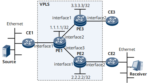
On the VPLS network shown in Figure 1, PE1, PE2, and PE3 are responsible for transmitting multicast data from the IPTV server to downstream receivers.
To control the multicast group number over the VPLS network, configure the Layer 2 multicast entry limit for the VSI on PEs to prevent the bandwidth resources from exceeding the total bandwidth of the aggregation network and ensure service quality for most subscribers.
The required Layer 2 multicast entry limit configurations on PEs are as follows:
- On PE1, limit the number of multicast groups to 10 in the VSI vsi1.
- On PE3, limit the number of multicast groups on the PW (with the remote-peer address of 1.1.1.1) to 10.

Interfaces 1 through 3 in this example represent GE 0/1/0, GE 0/1/1, and GE 0/1/2, respectively.
Device |
Interface |
IP Address |
|---|---|---|
PE1 |
GE 0/1/1 |
192.168.0.1/30 |
GE 0/1/2 |
192.168.1.1/30 |
|
PE2 |
GE 0/1/0 |
192.168.1.2/30 |
PE3 |
GE 0/1/0 |
192.168.0.2/30 |
Configuration Roadmap
The configuration roadmap is as follows:
Configure basic MPLS and L2VPN functions on each device to ensure that multicast services run properly on the VPLS network.
Create the VSI on each device and create a PW between PE1 and PE3 so that virtual tunnels can be set up between them.
Configure IGMP snooping globally and in the VSI to manage the forwarding of multicast data packets to implement on-demand multicast data distribution on the Layer 2 VPLS network and reduce bandwidth usage at both the user side and network side.
Configure the multicast group number limit for the VSI on PE1.
Configure the multicast group number limit for the PW on PE3.
Data Preparation
To complete the configuration, you need the following data:
IP addresses of the interfaces and loopback address of each device
IP routing protocol (IS-IS is used in this example and the process ID is 1)
MPLS Label Switch Router (LSR) ID of each device (consistent with loopback address of each device)
VSI name (vsi1 is used in this example) used to set up a PW between PEs
Sub-interface bound to the VSI on each PE and VLAN to which users belong (GE 0/1/1.1 and VLAN 11 are used in this example)
Multicast group number limit
Procedure
- Configure IS-IS to make router interfaces reachable. (Configuration procedures are not detailed here.)
- Enable MPLS and Label Distribution Protocol (LDP) on the MPLS backbone network and enable L2VPN. (Configuration procedures are not detailed here.)
- Enable MPLS L2VPN and configure a VSI.
# Configure PE1.
[~PE1] mpls l2vpn
[*PE1-l2vpn] quit
[~PE1] vsi vsi1 static
[*PE1-vsi-vsi1] pwsignal ldp
[*PE1-vsi-vsi1-ldp] vsi-id 123
[*PE1-vsi-vsi1-ldp] peer 3.3.3.3
[*PE1-vsi-vsi1-ldp] quit
[*PE1-vsi-vsi1] quit
[*PE1] commit
# Configure PE3.
[~PE3] mpls l2vpn
[*PE3-l2vpn] quit
[~PE3] vsi vsi1 static
[*PE3-vsi-vsi1] pwsignal ldp
[*PE3-vsi-vsi1-ldp] vsi-id 123
[*PE3-vsi-vsi1-ldp] peer 1.1.1.1
[*PE3-vsi-vsi1-ldp] quit
[*PE3-vsi-vsi1] quit
[*PE3] commit
- Bind the VSI to a sub-interface on each PE.
# Configure PE1.
[~PE1] interface gigabitethernet0/1/0.1
[*PE1-GigabitEthernet0/1/0.1] vlan-type dot1q 11
[*PE1-GigabitEthernet0/1/0.1] l2 binding vsi vsi1
[*PE1-GigabitEthernet0/1/0.1] quit
[*PE1] commit
# Configure PE3.
[~PE3] interface gigabitethernet0/1/1.1
[*PE3-GigabitEthernet0/1/0.1] vlan-type dot1q 11
[*PE3-GigabitEthernet0/1/0.1] l2 binding vsi vsi1
[*PE3-GigabitEthernet0/1/0.1] quit
[*PE3] commit
- Verify the configuration.
After the preceding configurations are complete, run the display vsi command on each PE to check the VSI status. The following example uses the command output on PE1. The command output shows that the VSI is Up.
[~PE1] display vsi Total VSI number is 1, 1 is up, 0 is down, 1 is LDP mode, 0 is BGP mode Vsi Mem PW Mac Encap Mtu Vsi Name Disc Type Learn Type Value State -------------------------------------------------------------------------- vsi1 static ldp unqualify vlan 1500 up - Enable IGMP snooping globally and for the VSI on PE1 and PE3.
# Configure PE1. The configurations on PE3 are similar to those on PE1.
[~PE1] igmp-snooping enable
[*PE1] vsi vsi1
[*PE1-vsi-vsi1] igmp-snooping enable
[*PE1-vsi-vsi1] quit
[*PE1] commit
- Configure GE 0/1/0.1 on PE1 a static router ports.
# Configure PE1.
[~PE1] interface gigabitethernet 0/1/0.1
[~PE1-GigabitEthernet0/1/0.1] igmp-snooping static-router-port vsi vsi1
[*PE1-GigabitEthernet0/1/0.1] quit
[*PE1] commit
- Configure the multicast group number limit for the VSI on PE1.
# Configure PE1.
[~PE1] vsi vsi1
[~PE1-vsi-vsi1] l2-multicast limit max-entry 10
[*PE1-vsi-vsi1] quit
[*PE1] commit
- Configure the multicast group number limit for the PW on PE3.
# Configure PE3.
[~PE3] vsi vsi1
[~PE3-vsi-vsi1] pwsignal ldp
[*PE3-vsi-vsi1-ldp] l2-multicast limit max-entry 10 remote-peer 1.1.1.1
[*PE3-vsi-vsi1-ldp] quit
[*PE3-vsi-vsi1] quit
[*PE3] commit
- Verify the configuration.
# After completing the configurations, run the display l2-multicast limit command on PE1 to view the configured entry limit information. The command output is as follows:
[~PE1]  display l2-multicast limit
L2-multicast limit information
------------------------------------------------------------------------------
                                               ConfigEntries
                                               CurrentEntries
------------------------------------------------------------------------------
VSI vsi1 limit information:
------------------------------------------------------------------------------
                                               10
                                               5
# Run the display l2-multicast limit command on PE3 to view the configured entry limit information. The command output is as follows:
[~PE3] display l2-multicast limit
L2-multicast limit information
------------------------------------------------------------------------------
                                               ConfigEntries
                                               CurrentEntries
------------------------------------------------------------------------------
PW(Peer:1.1.1.1, VCID:111) limit information:
------------------------------------------------------------------------------
                                               10
                                               3
------------------------------------------------------------------------------
Configuration Files
PE1 configuration file
#
 sysname PE1
#
 vlan batch 11
#
 igmp-snooping enable
#
 mpls lsr-id 1.1.1.1
 mpls
#
 mpls l2vpn
#
vsi vsi1 static
 pwsignal ldp
  vsi-id 123
  peer 3.3.3.3
 igmp-snooping enable
 l2-multicast limit max-entry 10
#
mpls ldp
#
isis 1
 is-level level-1
 network-entity 49.0010.0100.1001.00
#
interface GigabitEthernet0/1/0.1
 vlan-type dot1q 11
 l2 binding vsi vsi1
 igmp-snooping static-router-port vsi vsi1
#
interface GigabitEthernet0/1/1
 undo shutdown
 ip address 192.168.0.1 255.255.255.252
 isis enable 1
 mpls
 mpls ldp
#
interface LoopBack0
 ip address 1.1.1.1 255.255.255.255
 isis enable 1
#
return
PE3 configuration file
#
 sysname PE3
#
 vlan batch 11
#
 mpls lsr-id 3.3.3.3
 mpls
#
 mpls l2vpn
#
vsi vsi1 static
 pwsignal ldp
  vsi-id 123
  peer 1.1.1.1
  l2-multicast limit max-entry 10 remote-peer 1.1.1.1
#
mpls ldp
#
isis 1
 is-level level-1
 network-entity 49.0030.0300.3003.00
#
interface GigabitEthernet0/1/0
 undo shutdown
 ip address 192.168.0.2 255.255.255.0
 isis enable 1
 mpls
 mpls ldp
#
interface GigabitEthernet0/1/1.1
 vlan-type dot1q 11
 l2 binding vsi vsi1
#
interface LoopBack0
 ip address 3.3.3.3 255.255.255.255
 isis enable 1
#
return