Example for Configuring Layer 2 Multicast CAC for a VSI
This section provides an example for configuring Layer 2 multicast CAC for a VSI.
Networking Requirements
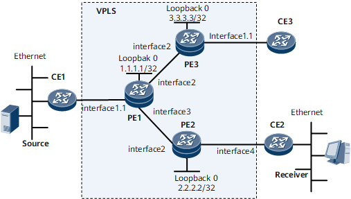
On the VPLS network shown in Figure 1, PE1, PE2, and PE3 are responsible for transmitting multicast data from a source device to downstream receivers.
To limit the multicast group quantity and bandwidth over the VPLS network, configure Layer 2 multicast CAC for the VSI on each PE to prevent the needed bandwidth from exceeding the total bandwidth of the access or aggregation network and ensure service quality for subscribers. Layer 2 multicast CAC also helps service providers to control the number or bandwidth of multicast groups in each channel.
Configure Layer 2 multicast CAC on each PE as follows:
- On PE1, set the maximum number of multicast groups to 10 in the VSI named vsi1.
- On PE2, create an ASM channel tv1 in vsi1, set the multicast group address to 225.0.0.1/24 for the channel, and limit the bandwidth to 10 kbit/s for each multicast group member. Limit the multicast group bandwidth to 2500 kbit/s on GE 0/1/1.1 of PE2.
- On PE3, set the maximum number of multicast groups to 10 for the VSI with the remote-peer address 1.1.1.1.

Interface 1.1, interface 2, interface 3, and interface 4 in this example represent GE 0/1/0.1, GE 0/1/1, GE 0/1/2, and Eth-Trunk 1.1, respectively.
Device |
Interface |
IP Address |
|---|---|---|
PE1 |
GE 0/1/1 |
10.1.1.1/24 |
GE 0/1/2 |
10.1.2.1/24 |
|
Loopback 0 |
1.1.1.1/32 |
|
PE2 |
GE 0/1/1 |
10.1.1.2/24 |
Loopback 0 |
2.2.2.2/32 |
|
PE3 |
GE 0/1/1 |
10.1.2.2/24 |
Loopback 0 |
3.3.3.3/32 |
Configuration Roadmap
The configuration roadmap is as follows:
Assign an IP address for each interface and configure a routing protocol to ensure IP connectivity at the network layer. In this example, OSPF is used.
Configure basic MPLS LDP functions on PE1, PE2, and PE3.
Configure an LDP-based VSI and complete basic VSI configurations.
Configure IGMP snooping globally and in the VSI to manage the forwarding of multicast data messages to implement on-demand multicast data distribution on the Layer 2 VPLS network and reduce bandwidth usage at both the user side and network side.
On PE1, set the maximum number of multicast groups in the VSI.
Configure a VSI-based channel on PE2.
Configure multicast CAC on the sub-interface of PE2.
Configure the maximum number of multicast groups for the PW on PE3.
Data Preparation
To complete the configuration, you need the following data:
IP addresses of all interfaces, including loopback interfaces, listed in Figure 1
OSPF process ID 1, and area ID 0.0.0.0 for each PE
MPLS LSR ID of each device (same as the loopback address of each device)
VSI name vsi1, and VSI ID 100
Sub-interface GE 0/1/0.1 to be bound to the VSI on each PE and user-side VLAN 11
Layer 2 multicast CAC parameters
Procedure
- Assign an IP address for each interface and configure OSPF.
For configuration details, see Configuration Files in this section.
- Configure basic MPLS LDP functions on PE1, PE2, and PE3.
For configuration details, see Configuration Files in this section.
- Configure an LDP-based VSI.
# Configure PE1.
[~PE1] mpls l2vpn
[*PE1-l2vpn] commit
[*PE1-l2vpn] quit
[~PE1] vsi vsi1
[*PE1-vsi-vsi1] pwsignal ldp
[*PE1-vsi-vsi1-ldp] vsi-id 100
[*PE1-vsi-vsi1-ldp] peer 2.2.2.2
[*PE1-vsi-vsi1-ldp] peer 3.3.3.3
[*PE1-vsi-vsi1-ldp] quit
[*PE1-vsi-vsi1] quit
[*PE1] commit
[~PE1] interface gigabitethernet0/1/0.1
[*PE1-GigabitEthernet0/1/0.1] vlan-type dot1q 11
[*PE1-GigabitEthernet0/1/0.1] l2 binding vsi vsi1
[*PE1-GigabitEthernet0/1/0.1] quit
[*PE1] commit
The configurations of PE2 and PE3 are similar to the configuration of PE1. For configuration details, see Configuration Files in this section.
- After the preceding configurations are complete, run the display vsi command on each PE to check the VSI status.
The following example uses the command output on PE1. The VSI is Up.
[~PE1] display vsi Total VSI number is 1, 1 is up, 0 is down, 1 is LDP mode, 0 is BGP mode, 0 is BG PAD mode, 0 is mixed mode, 0 is unspecified mode -------------------------------------------------------------------------- Vsi Mem PW Mac Encap Mtu Vsi Name Disc Type Learn Type Value State -------------------------------------------------------------------------- vsi1 -- ldp unqualify vlan 1500 up - Enable IGMP snooping globally and for the VSI on PE1, PE2, and PE3.
# Configure PE1.
[~PE1] igmp-snooping enable
[*PE1] commit
[~PE1] vsi vsi1
[*PE1-vsi-vsi1] igmp-snooping enable
[*PE1-vsi-vsi1] quit
[*PE1] commit
Repeat this step for PE2 and PE3. For configuration details, see Configuration Files in this section.
- Configure GE 0/1/1.1 on PE1 as a static router port.
# Configure PE1.
[~PE1] interface gigabitethernet 0/1/0.1
[~PE1-GigabitEthernet0/1/0.1] igmp-snooping static-router-port vsi vsi1
[*PE1-GigabitEthernet0/1/0.1] quit
[*PE1] commit
# Configure PE2.
[~PE2] vsi vsi1
[*PE2-vsi-vsi1] igmp-snooping static-router-port remote-peer 1.1.1.1
[*PE2-vsi-vsi1] quit
[*PE2] commit
- Set the maximum number of multicast groups in the VSI on PE1.
[~PE1] vsi vsi1
[*PE1-vsi-vsi1] l2-multicast limit max-entry 10
[*PE1-vsi-vsi1] quit
[*PE1] commit
- Configure a VSI-based channel on PE2.
# Configure PE2.
[~PE2] l2-multicast-channel vsi vsi1
[*PE2-l2-channel-vsi-vsi1] channel tv1 type asm
[*PE2-l2-channel-vsi-vsi1-tv1] group 225.0.0.1 24 per-bandwidth 10
[*PE2-l2-channel-vsi-vsi1-tv1] quit
[*PE2-l2-channel-vsi-vsi1] quit
[*PE2] commit
- Configure multicast CAC on the sub-interface of PE2.
# Configure PE2.
[~PE2] interface Eth-Trunk 1.1
[~PE2--Eth-Trunk1.1] encapsulation dot1q-termination
[~PE2--Eth-Trunk1.1] dot1q termination vid 11
[~PE2--Eth-Trunk1.1] l2 binding vsi vsi1
[*PE2--Eth-Trunk1.1] l2-multicast limit channel tv1 bandwidth 2500 dot1q vid 11
[*PE2--Eth-Trunk1.1] quit
[*PE2] commit
- Configure the maximum number of multicast groups for the PW on PE3.
# Configure PE3.
[~PE3] vsi vsi1
[*PE3-vsi-vsi1] pwsignal ldp
[*PE3-vsi-vsi1-ldp] l2-multicast limit max-entry 10 remote-peer 1.1.1.1
[*PE3-vsi-vsi1-ldp] quit
[*PE3-vsi-vsi1] quit
[*PE3] commit
- Verify the configuration.
# Run the display l2-multicast limit command on PE1 and PE2 to view Layer 2 multicast CAC configurations.
[~PE1] display l2-multicast limit
L2-multicast limit information, The unit of bandwidth is Kbits/sec
------------------------------------------------------------------------------
                                               ConfigEntries  ConfigBandwidth
                                               CurrentEntries CurrentBandwidth
------------------------------------------------------------------------------
VSI vsi1 limit information:
------------------------------------------------------------------------------
                                               10             ----------
                                               0              ----------
[~PE2] display l2-multicast limit
L2-multicast limit information, The unit of bandwidth is Kbits/sec
------------------------------------------------------------------------------
                                               ConfigEntries  ConfigBandwidth
                                               CurrentEntries CurrentBandwidth
------------------------------------------------------------------------------
interface Eth-Trunk1.1 dot1q vid 11 limit information:
------------------------------------------------------------------------------
                                       tv1     ----           2500
                                               ----           0
# Run the display l2-multicast-channel command on PE2 to view channel information.
[~PE2] display l2-multicast-channel
Channel information on VSI vsi1
 ChannelName                    Group/Mask         Source/Mask        Bandwidth
-------------------------------------------------------------------------------
 tv1                            225.0.0.0/24       *                  10
-------------------------------------------------------------------------------
# Run the display l2-multicast limit command on PE3 to view Layer 2 multicast CAC configurations.
[~PE3] display l2-multicast limit
L2-multicast limit information, The unit of bandwidth is Kbits/sec
------------------------------------------------------------------------------
                                               ConfigEntries  ConfigBandwidth
                                               CurrentEntries CurrentBandwidth
------------------------------------------------------------------------------
PW(Peer:1.1.1.1, VCID:100) limit information:
------------------------------------------------------------------------------
                                               10
                                               0
------------------------------------------------------------------------------
Configuration Files
PE1 configuration file
#
sysname PE1
#
vlan batch 11
#
igmp-snooping enable
#
mpls lsr-id 1.1.1.1
#
mpls
#
mpls l2vpn
#
vsi vsi1
 pwsignal ldp
  vsi-id 100
  peer 2.2.2.2
  peer 3.3.3.3
 igmp-snooping enable
 l2-multicast limit max-entry 10
#
mpls ldp
 #
interface GigabitEthernet0/1/0
 undo shutdown
#
interface GigabitEthernet0/1/0.1
 vlan-type dot1q 11
 l2 binding vsi vsi1
 igmp-snooping static-router-port vsi vsi1
#
interface GigabitEthernet0/1/1
 undo shutdown
 ip address 10.1.1.1 255.255.255.0
 mpls
 mpls ldp
#
interface GigabitEthernet0/1/2
 undo shutdown
 ip address 10.1.2.1 255.255.255.0
 mpls
 mpls ldp
#
interface LoopBack0
 ip address 1.1.1.1 255.255.255.255
#
ospf 1
 area 0.0.0.0
  network 1.1.1.1 0.0.0.0
  network 10.1.1.0 0.0.0.255
  network 10.1.2.0 0.0.0.255
#
return
PE2 configuration file
#
sysname PE2
#
vlan batch 11
#
igmp-snooping enable
#
mpls lsr-id 2.2.2.2
#
mpls
#
mpls l2vpn
#
vsi vsi1
 pwsignal ldp
  vsi-id 100
  peer 1.1.1.1
 igmp-snooping enable
 igmp-snooping static-router-port remote-peer 1.1.1.1
#
mpls ldp
#
interface Eth-Trunk1
#
interface Eth-Trunk1.1
 encapsulation dot1q-termination
 dot1q termination vid 11
 l2 binding vsi vsi1
 l2-multicast limit channel tv1 bandwidth 2500 dot1q vid 11
#
interface GigabitEthernet0/1/1
 undo shutdown
 ip address 10.1.1.2 255.255.255.0
 mpls
 mpls ldp
#
interface LoopBack0
 ip address 2.2.2.2 255.255.255.255
#
ospf 1
 area 0.0.0.0
  network 2.2.2.2 0.0.0.0
  network 10.1.1.0 0.0.0.255
#
l2-multicast-channel vsi vsi1
 channel tv1 type asm
  group 225.0.0.0 255.255.255.0 per-bandwidth 10
#
return
PE3 configuration file
#
sysname PE3
#
vlan batch 11
#
igmp-snooping enable
#
mpls lsr-id 3.3.3.3
#
mpls
#
mpls l2vpn
#
vsi vsi1
 pwsignal ldp
  vsi-id 100
  peer 1.1.1.1
  l2-multicast limit max-entry 10 remote-peer 1.1.1.1
 igmp-snooping enable
 igmp-snooping static-router-port remote-peer 1.1.1.1
#
mpls ldp
#
interface GigabitEthernet0/1/0
 undo shutdown
#
interface GigabitEthernet0/1/0.1
 vlan-type dot1q 11
 l2 binding vsi vsi1
 igmp-snooping static-router-port vsi vsi1
#
interface GigabitEthernet0/1/1
 undo shutdown
 ip address 10.1.2.2 255.255.255.0
 mpls
 mpls ldp
#
interface LoopBack0
 ip address 3.3.3.3 255.255.255.255
#
ospf 1
 area 0.0.0.0
  network 3.3.3.3 0.0.0.0
  network 10.1.2.0 0.0.0.255
#
return