Example for Configuring a Layer 2 Multicast Instance for VSI Users
This section provides an example for configuring a Layer 2 multicast instance for VSI users who request for the same multicast group's data from the same source.
Networking Requirements
In conventional multicast on-demand mode, if users of a Layer 2 multicast device in different VSIs request for the same multicast group's data from the same source, the connected upstream Layer 3 device has to send a copy of each multicast flow of this group for each VSI. Such implementation wastes bandwidth resources and burdens the upstream device. On the network shown in Figure 1, PE1 and PE2 connect to users. PE1 and PE2 are connected over a VPLS network. Users in different VSIs request for the same multicast group's data from the same source.
To enable PE1 to request for only one copy of each flow for all the users in the VSIs, configure a Layer 2 multicast instance. To facilitate data forwarding management, specify a multicast channel for the Layer 2 multicast instance.
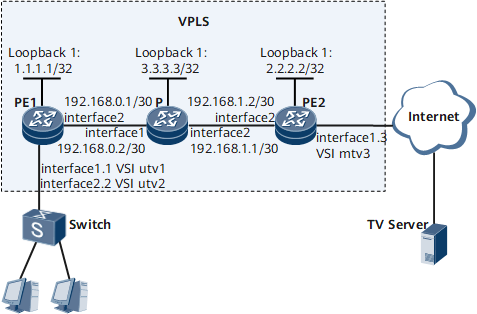

Interface 1, interface 2, interface 1.1, interface 1.2, and interface 1.3 in this example represent GE 0/1/0, GE 0/1/8, GE 0/1/0.1, GE 0/1/0.2, and GE 0/1/0.3, respectively.
Configuration Roadmap
The configuration roadmap is as follows:
Assign IP addresses for interfaces and configure basic MPLS functions to ensure the VPLS network connectivity.
Configure VSIs and enable basic IGMP snooping functions.
Configure static Layer 2 multicast groups for VSIs.
Create a Layer 2 multicast instance.
Specify a channel for the Layer 2 multicast instance.
Configure the multicast instance and user instances for the Layer 2 multicast instance.
Data Preparation
To complete the configuration, you need the following data:
Interface IP addresses (including the loopback interface addresses) and IS-IS process ID
Multicast channel addresses and static multicast group addresses
Name of the VSI to be configured as the multicast instance, and names of the VSIs to be configured as user instances
Procedure
- Configure IP addresses and IS-IS on PE1, PE2, and the P.
# Configure PE1.
<HUAWEI> system-view
[~HUAWEI] sysname PE1
[*HUAWEI] commit
[~PE1] interface LoopBack 1
[*PE1-LoopBack1] ip address 1.1.1.1 32
[*PE1-LoopBack1] quit
[*PE1] interface GigabitEthernet 0/1/8
[*PE1-GigabitEthernet0/1/8] undo shutdown
[*PE1-GigabitEthernet0/1/8] ip address 192.168.0.1 30
[*PE1-GigabitEthernet0/1/8] quit
[*PE1] isis 1
[*PE1-isis-1] is-level level-1
[*PE1-isis-1] network-entity 49.0010.0100.1001.00
[*PE1-isis-1] quit
[*PE1] interface GigabitEthernet 0/1/8
[*PE1-GigabitEthernet0/1/8] isis enable
[*PE1-GigabitEthernet0/1/8] quit
[*PE1] interface LoopBack 1
[*PE1-LoopBack1] isis enable
[*PE1-LoopBack1] commit
[~PE1-LoopBack1] quit
# Configure PE2.
<HUAWEI> system-view
[~HUAWEI] sysname PE2
[*PE2] commit
[~PE2] interface LoopBack 1
[*PE2-LoopBack1] ip address 2.2.2.2 32
[*PE2-LoopBack1] quit
[*PE2] interface GigabitEthernet 0/1/8
[*PE2-GigabitEthernet0/1/8] undo shutdown
[*PE2-GigabitEthernet0/1/8] ip address 192.168.1.2 30
[*PE2-GigabitEthernet0/1/8] quit
[*PE2] isis 1
[*PE2-isis-1] is-level level-1
[*PE2-isis-1] network-entity 49.0020.0200.2002.00
[*PE2-isis-1] quit
[*PE2] interface GigabitEthernet 0/1/8
[*PE2-GigabitEthernet0/1/8] isis enable
[*PE2-GigabitEthernet0/1/8] quit
[*PE2] interface LoopBack 1
[*PE2-LoopBack1] isis enable
[*PE2-LoopBack1] commit
[~PE2-LoopBack1] quit
# Configure the P.
<HUAWEI> system-view
[~HUAWEI] sysname P
[*HUAWEI] commit
[~P] interface LoopBack 1
[*P-LoopBack1] ip address 3.3.3.3 32
[*P-LoopBack1] quit
[*P] interface GigabitEthernet 0/1/0
[*P-GigabitEthernet0/1/0] undo shutdown
[*P-GigabitEthernet0/1/0] ip address 192.168.0.2 30
[*P-GigabitEthernet0/1/0] quit
[*P] interface GigabitEthernet 0/1/8
[*P-GigabitEthernet0/1/8] undo shutdown
[*P-GigabitEthernet0/1/8] ip address 192.168.1.1 30
[*P-GigabitEthernet0/1/8] quit
[*P] isis 1
[*P-isis-1] is-level level-1
[*P-isis-1] network-entity 49.0030.0300.3003.00
[*P-isis-1] quit
[*P] interface LoopBack 1
[*P-LoopBack1] isis enable
[*P-LoopBack1] quit
[*P] interface GigabitEthernet 0/1/0
[*P-GigabitEthernet0/1/0] isis enable
[*P-GigabitEthernet0/1/0] quit
[*P] interface GigabitEthernet 0/1/8
[*P-GigabitEthernet0/1/8] isis enable
[*P-GigabitEthernet0/1/8] commit
[~P-GigabitEthernet0/1/8] quit
- Configure basic MPLS functions and LDP on PE1, PE2, and the P.
# Configure PE1.
[~PE1] mpls lsr-id 1.1.1.1
[*PE1] mpls
[*PE1-mpls] quit
[*PE1] mpls ldp
[*PE1-mpls-ldp] quit
[*PE1] interface GigabitEthernet 0/1/8
[~PE1-GigabitEthernet0/1/8] mpls
[*PE1-GigabitEthernet0/1/8] mpls ldp
[*PE1-GigabitEthernet0/1/8] commit
[~PE1-GigabitEthernet0/1/8] quit
# Configure PE2.
[~PE2] mpls lsr-id 2.2.2.2
[*PE2] mpls
[*PE2-mpls] quit
[*PE2] mpls ldp
[*PE2-mpls-ldp] quit
[*PE2] interface GigabitEthernet 0/1/8
[~PE2-GigabitEthernet0/1/8] mpls
[*PE2-GigabitEthernet0/1/8] mpls ldp
[*PE2-GigabitEthernet0/1/8] commit
[~PE2-GigabitEthernet0/1/8] quit
# Configure the P.
[~P] mpls lsr-id 3.3.3.3
[*P] mpls
[*P-mpls] quit
[*P] mpls ldp
[*P-mpls-ldp] quit
[*P] interface GigabitEthernet 0/1/0
[~P-GigabitEthernet0/1/0] mpls
[*P-GigabitEthernet0/1/0] mpls ldp
[*P-GigabitEthernet0/1/0] quit
[*P] interface GigabitEthernet 0/1/8
[~P-GigabitEthernet0/1/8] mpls
[*P-GigabitEthernet0/1/8] mpls ldp
[*P-GigabitEthernet0/1/8] commit
[~P-GigabitEthernet0/1/8] quit
- Specify remote peer names and IP addresses on PE1 and PE2 to establish an LDP session.
# Configure PE1.
[~PE1] mpls ldp remote-peer PE2
[*PE1-mpls-ldp-remote-PE2] remote-ip 2.2.2.2
[*PE1-mpls-ldp-remote-PE2] commit
[~PE1-mpls-ldp-remote-PE2] quit
# Configure PE2.
[*PE2]mpls ldp remote-peer PE1
[*PE2-mpls-ldp-remote-PE1] remote-ip 1.1.1.1
[*PE2-mpls-ldp-remote-PE1] commit
[~PE2-mpls-ldp-remote-PE1] quit
- Verify the MPLS configuration.
After completing the configurations, run the display mpls ldp session command on PE1 and PE2. A remote LDP session has been established successfully between PE1 and PE2 if the command output shows the session status as Operational.
The following example uses the command output on PE1.
[PE1] display mpls ldp session
 LDP Session(s) in Public Network
 Codes: LAM(Label Advertisement Mode), SsnAge Unit(DDDD:HH:MM)
 A '*' before a session means the session is being deleted.
 ------------------------------------------------------------------------------
 PeerID             Status      LAM  SsnRole  SsnAge      KASent/Rcv
 ------------------------------------------------------------------------------
 3.3.3.3:0          Operational DU   Passive  0001:00:04  5780/5780
 2.2.2.2:0          Operational DU   Passive  0001:03:17  6552/6552
 ------------------------------------------------------------------------------
 TOTAL: 2 session(s) Found.
Run the display mpls ldp remote-peer command on PE1 and PE2 to check remote peer information.
The following example uses the command output on PE1.
[PE1] display mpls ldp remote-peer LDP Remote Entity Information ------------------------------------------------------------------------------ Remote Peer Name : peb Description : ---- Remote Peer IP : 2.2.2.2 LDP ID : 1.1.1.1:0 Transport Address : 1.1.1.1 Entity Status : Active Configured Keepalive Hold Timer : 45 Sec Configured Keepalive Send Timer : --- Configured Hello Hold Timer : 45 Sec Negotiated Hello Hold Timer : 45 Sec Configured Hello Send Timer : --- Configured Delay Timer : 10 Sec Hello Packet sent/received : 6562/6561 Remote Peer Deletion Status : No ------------------------------------------------------------------------------ TOTAL: 1 Peer(s) Found. - Enable MPLS L2VPN and configure VSIs.
# Configure PE1.
[~PE1] mpls l2vpn
[*PE1-l2vpn] quit
[*PE1] vsi mtv3 static
[*PE1-vsi-mtv3] pwsignal ldp
[*PE1-vsi-mtv3-ldp] vsi-id 3
[*PE1-vsi-mtv3-ldp] peer 2.2.2.2
[*PE1-vsi-mtv3-ldp] quit
[*PE1-vsi-mtv3] quit
[*PE1] vsi utv2 static
[*PE1-vsi-utv2] pwsignal ldp
[*PE1-vsi-utv2-ldp] vsi-id 2
[*PE1-vsi-utv2-ldp] peer 2.2.2.2
[*PE1-vsi-utv2-ldp] quit
[*PE1-vsi-utv2] quit
[*PE1] vsi utv1 static
[*PE1-vsi-utv1] pwsignal ldp
[*PE1-vsi-utv1-ldp] vsi-id 1
[*PE1-vsi-utv1-ldp] peer 2.2.2.2
[*PE1-vsi-utv1-ldp] commit
[~PE1-vsi-utv1-ldp] quit
[~PE1-vsi-utv1] quit
# Configure PE2.
[~PE2] mpls l2vpn
[*PE2-l2vpn] quit
[*PE2] vsi mtv3 static
[*PE2-vsi-mtv3] pwsignal ldp
[*PE2-vsi-mtv3-ldp] vsi-id 3
[*PE2-vsi-mtv3-ldp] peer 1.1.1.1
[*PE2-vsi-mtv3-ldp] quit
[*PE2-vsi-mtv3] quit
[*PE2] vsi utv2 static
[*PE2-vsi-utv2] pwsignal ldp
[*PE2-vsi-utv2-ldp] vsi-id 2
[*PE2-vsi-utv2-ldp] peer 1.1.1.1
[*PE2-vsi-utv2-ldp] quit
[*PE2-vsi-utv2] quit
[*PE2] vsi utv1 static
[*PE2-vsi-utv1] pwsignal ldp
[*PE2-vsi-utv1-ldp] vsi-id 1
[*PE2-vsi-utv1-ldp] peer 1.1.1.1
[*PE2-vsi-utv1-ldp] commit
[~PE2-vsi-utv1-ldp] quit
[~PE2-vsi-utv1] quit
- Enable IGMP snooping on PE1.
[~PE1] igmp-snooping enable
[*PE1] commit
- On PE1 and PE2, bind sub-interfaces to VSIs. On PE1, configure Layer 2 static multicast groups for the sub-interface bound to the VSI named utv1 and for that bound to the VSI named utv2.
# Configure PE1.
[~PE1] vlan 3
[*PE1-vlan3] quit
[*PE1] interface gigabitethernet 0/1/0.3
[~PE1-GigabitEthernet0/1/0.3] vlan-type dot1q 3
[*PE1-GigabitEthernet0/1/0.3] l2 binding vsi mtv3
[*PE1-GigabitEthernet0/1/0.3] quit
[*PE1] vlan 11
[*PE1-vlan11] quit
[*PE1] interface gigabitethernet 0/1/0.1
[~PE1-GigabitEthernet0/1/0.1] vlan-type dot1q 11
[*PE1-GigabitEthernet0/1/0.1] l2 binding vsi utv1
[*PE1-GigabitEthernet0/1/0.1] l2-multicast static-group group-address 226.0.0.1 vsi utv1
[*PE1-GigabitEthernet0/1/0.1] quit
[*PE1] vlan 22
[*PE1-vlan22] quit
[*PE1] interface gigabitethernet 0/1/0.2
[~PE1-GigabitEthernet0/1/0.2] vlan-type dot1q 22
[*PE1-GigabitEthernet0/1/0.2] l2 binding vsi utv2
[*PE1-GigabitEthernet0/1/0.2] l2-multicast static-group group-address 226.0.0.1 vsi utv2
[*PE1-GigabitEthernet0/1/0.2] commit
[~PE1-GigabitEthernet0/1/0.2] quit
# Configure PE2.
[~PE2] vlan 3
[*PE2-vlan3] quit
[*PE2] interface gigabitethernet 0/1/0.3
[~PE2-GigabitEthernet0/1/0.3] vlan-type dot1q 3
[*PE2-GigabitEthernet0/1/0.3] l2 binding vsi mtv3
[*PE2-GigabitEthernet0/1/0.3] quit
[*PE2] vlan 11
[*PE2-vlan11] quit
[*PE2] interface gigabitethernet 0/1/0.1
[~PE2-GigabitEthernet0/1/0.1] vlan-type dot1q 11
[*PE2-GigabitEthernet0/1/0.1] l2 binding vsi utv1
[*PE2-GigabitEthernet0/1/0.1] quit
[*PE2] vlan 22
[*PE2-vlan22] quit
[*PE2] interface gigabitethernet 0/1/0.2
[~PE2-GigabitEthernet0/1/0.2] vlan-type dot1q 22
[*PE2-GigabitEthernet0/1/0.2] l2 binding vsi utv2
[*PE2-GigabitEthernet0/1/0.2] commit
[~PE2-GigabitEthernet0/1/0.2] quit
- After completing the configurations, run the display vsi command to check VSI status.
The following example uses the command output on PE1. The command output shows that all the VSIs are Up.
[PE1] display vsi
Total VSI number is 3, 3 is up, 0 is down, 3 is LDP mode, 0 is BGP mode

Vsi                             Mem    PW   Mac       Encap     Mtu   Vsi
Name                            Disc   Type Learn     Type      Value State
--------------------------------------------------------------------------
mtv3                            static ldp  unqualify vlan      1500  up
utv2                            static ldp  unqualify vlan      1500  up
utv1                            static ldp  unqualify vlan      1500  up
- On PEs, enable IGMP snooping for the VSI named mtv3.
# On PE1, enable IGMP snooping.
[~PE1] vsi mtv3
[*PE1-VSI-mtv3] igmp-snooping enable
[*PE1-VSI-mtv3] quit
# On PE2, enable IGMP snooping.
[~PE2] vsi mtv3
[*PE2-VSI-mtv3] igmp-snooping enable
[*PE2-VSI-mtv3] quit
- Create a Layer 2 multicast instance and enter the instance view.
[~PE1] l2-multicast instance 1 - Specify a multicast channel for the Layer 2 multicast instance.
[*PE1-l2-minst1] import-channel 226.0.0.0 24 - Configure a VSI as the multicast instance for the Layer 2 multicast instance.
[*PE1-l2-minst1] multicast-instance vsi mtv3 - Configure VSIs as user instances for the Layer 2 multicast instance.
[*PE1-l2-minst1] user-instance vsi utv1
[*PE1-l2-minst1] user-instance vsi utv2
[*PE1-l2-minst1] commit
[~PE1-l2-minst1] quit
- Verify the configuration.
# After completing the configurations, run the display l2-multicast instance command on PE1 to check information about the multicast instance, user instances, and channel of the Layer 2 multicast instance.
[PE1] display l2-multicast instance
L2-multicast instance ID: 1
Multicast-instance: VSI mtv3
Multicast channels:
 226.0.0.0/24
User-instance count: 2
User-instance List:
VSI List:
 VSI utv1
 VSI utv2
Configuration Files
PE1 configuration file
#
 sysname PE1
#
 igmp-snooping enable
#
 mpls lsr-id 1.1.1.1
 mpls
#
 mpls l2vpn
#
vsi mtv3 static
 pwsignal ldp
  vsi-id 3
  peer 2.2.2.2
 igmp-snooping enable
#
vsi utv2 static
 pwsignal ldp
  vsi-id 2
  peer 2.2.2.2
#
vsi utv1 static
 pwsignal ldp
  vsi-id 1
  peer 2.2.2.2
#
mpls ldp
#
 mpls ldp remote-peer pe2
 remote-ip 2.2.2.2
isis 1
 is-level level-1
 network-entity 49.0010.0100.1001.00
#
interface GigabitEthernet0/1/0.1
 vlan-type dot1q 11
 l2 binding vsi utv1
 l2-multicast static-group group-address 226.0.0.1 vsi utv1
#
interface GigabitEthernet0/1/0.2
 vlan-type dot1q 22
 l2 binding vsi utv2
 l2-multicast static-group group-address 226.0.0.1 vsi utv2
#
interface GigabitEthernet0/1/0.3
 vlan-type dot1q 3
 l2 binding vsi mtv3
#
interface GigabitEthernet0/1/8
 undo shutdown
 ip address 192.168.0.1 255.255.255.252
 isis enable 1
 mpls
 mpls ldp
#
interface LoopBack1
 ip address 1.1.1.1 255.255.255.255
 isis enable 1
#
l2-multicast instance 1
 multicast-instance vsi mtv3
 import-channel 226.0.0.0 255.255.255.0
 user-instance vsi utv2
 user-instance vsi utv1
#
return
PE2 configuration file
#
 sysname PE2
#
 igmp-snooping enable
#
 mpls lsr-id 2.2.2.2
 mpls
#
 mpls l2vpn
#
vsi mtv3 static
 pwsignal ldp
  vsi-id 3
  peer 1.1.1.1
 igmp-snooping enable
#
vsi utv2 static
 pwsignal ldp
  vsi-id 2
  peer 1.1.1.1
#
vsi utv1 static
 pwsignal ldp
  vsi-id 1
  peer 1.1.1.1
#
mpls ldp
#
#
 mpls ldp remote-peer pe1
 remote-ip 1.1.1.1
isis 1
 is-level level-1
 network-entity 49.0020.0200.2002.00
#
interface GigabitEthernet0/1/0.1
 vlan-type dot1q 11
 l2 binding vsi utv1
#
interface GigabitEthernet0/1/0.2
 vlan-type dot1q 22
 l2 binding vsi utv2
#
interface GigabitEthernet0/1/0.3
 vlan-type dot1q 3
 l2 binding vsi mtv3
#
interface GigabitEthernet0/1/8
 undo shutdown
 ip address 192.168.1.2 255.255.255.252
 isis enable 1
 mpls
 mpls ldp
#
interface LoopBack1
 ip address 2.2.2.2 255.255.255.255
 isis enable 1
#
return
P configuration file
#
 sysname P
#
 mpls lsr-id 3.3.3.3
 mpls
#
mpls ldp
#
isis 1
 is-level level-1
 network-entity 49.0030.0300.3003.00
#
interface GigabitEthernet0/1/0
 undo shutdown
 ip address 192.168.0.2 255.255.255.252
 isis enable 1
 mpls
 mpls ldp
#
interface GigabitEthernet0/1/8
 undo shutdown
 ip address 192.168.1.1 255.255.255.252
 isis enable 1
 mpls
 mpls ldp
#
interface LoopBack1
 ip address 3.3.3.3 255.255.255.255
 isis enable 1
#
return