Example for Configuring a Layer 2 Multicast Instance for VLAN Users
This section provides an example for configuring a Layer 2 multicast instance for VLAN users who request for the same multicast group's data from the same source.
Networking Requirements
In conventional multicast on-demand mode, if users of a Layer 2 multicast device in different VLANs request for the same multicast group's data from the same source, the connected upstream Layer 3 device has to send a copy of each multicast flow of this group for each VLAN. Such implementation wastes bandwidth resources and burdens the upstream device. For example, on the network shown in Figure 1, the PE connects to a device on the multicast source side, and the CE connects to users. Users in VLANs 11 and 22 request for the same multicast group's data from the same source.
To enable the CE to request for only one single of each flow from the PE for all the users in the VLANs, configure a Layer 2 multicast instance. To facilitate data forwarding management, specify a multicast channel for the Layer 2 multicast instance.
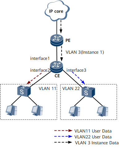

Interfaces 1 through 3 in this example represent GE 0/1/0, GE 0/1/8, and GE 0/1/16, respectively.
Configuration Roadmap
The configuration roadmap is as follows:
Configure VLANs and enable basic IGMP snooping functions.
Configure static Layer 2 multicast groups for VLANs.
Create a Layer 2 multicast instance.
Specify a channel for the Layer 2 multicast instance.
Configure the multicast instance and user instances for the Layer 2 multicast instance.
Data Preparation
To complete the configuration, you need the following data:
Multicast channel addresses and static multicast group addresses
ID of the VLAN to be configured as the multicast instance, and IDs of the VLANs to be configured as user instances
Procedure
- Create VLANs.
# Create VLANs on the CE.
<HUAWEI> system-view
[~HUAWEI] sysname CE
[*HUAWEI] commit
[~CE] vlan 3
[*CE-vlan3] quit
[*CE] vlan 11
[*CE-vlan11] quit
[*CE] vlan 22
[*CE-vlan22] quit
[*CE] commit
- Enable IGMP snooping on the CE.
[~CE] igmp-snooping enable - On the CE, configure GE 0/1/8 to permit the data frames of VLAN 11, and add this interface to the multicast group 225.0.0.1.
[~CE] interface gigabitethernet 0/1/8
[*CE-GigabitEthernet0/1/8] undo shutdown
[*CE-GigabitEthernet0/1/8] portswitch
[*CE-GigabitEthernet0/1/8] port trunk allow-pass vlan 11
[*CE-GigabitEthernet0/1/8] l2-multicast static-group group-address 225.0.0.1 vlan 11
[*CE-GigabitEthernet0/1/8] commit
[~CE-GigabitEthernet0/1/8] quit
- On the CE, configure GE 0/1/16 to permit the data frames of VLAN 22, and add this interface to the multicast group 225.0.0.1.
[~CE] interface gigabitethernet 0/1/16
[*CE-GigabitEthernet0/1/16] undo shutdown
[*CE-GigabitEthernet0/1/16] portswitch
[*CE-GigabitEthernet0/1/16] port trunk allow-pass vlan 22
[*CE-GigabitEthernet0/1/16] l2-multicast static-group group-address 225.0.0.1 vlan 22
[*CE-GigabitEthernet0/1/16] commit
[~CE-GigabitEthernet0/1/16] quit
- On the CE, configure GE 0/1/0 to permit only the data frames of VLAN 3.
The following configurations apply only to the Layer 2 multicast instance deployment scenario. If a Layer 2 multicast instance will not be configured, you need to configure GE 0/1/8 to permit the data frames of both VLANs 11 and 22.
[~CE] interface gigabitethernet 0/1/0
[*CE-GigabitEthernet0/1/0] undo shutdown
[*CE-GigabitEthernet0/1/0] portswitch
[*CE-GigabitEthernet0/1/0] port trunk allow-pass vlan 3
[*CE-GigabitEthernet0/1/0] commit
[~CE-GigabitEthernet0/1/0] quit
- On the CE, enable IGMP snooping for VLAN 3.
[~CE] vlan 3
[~CE-vlan3] igmp-snooping enable
[*CE-vlan3] commit
[~CE-vlan3] quit
- Create a Layer 2 multicast instance and enter the instance view.
[~CE] l2-multicast instance 1 - Specify a multicast channel for the Layer 2 multicast instance.
[*CE-l2-minst1] import-channel 225.0.0.0 24 - Configure a VLAN as the multicast instance for the Layer 2 multicast instance.
[*CE-l2-minst1] multicast-instance vlan 3 - Configure VLANs as user instances for the Layer 2 multicast instance.
[*CE-l2-minst1] user-instance vlan 11 22
[*CE-l2-minst1] commit
[~CE-l2-minst1] quit
- Verify the configuration.
# Run the display l2-multicast instance command on the CE to check information about the multicast instance, user instances, and channel of the Layer 2 multicast instance.
[CE] display l2-multicast instance
L2-multicast instance ID: 1
Multicast-instance: VLAN 3
Multicast channels:
 225.0.0.0/24
User-instance count: 2
User-instance List:
VLAN List:
 VLAN 11 22
Configuration Files
CE configuration file
#
 sysname CE
#
 vlan batch 3 11 22
#
 igmp-snooping enable
#
vlan 3
 igmp-snooping enable
#
interface GigabitEthernet0/1/0
 portswitch
 undo shutdown
 port trunk allow-pass vlan 3
#
interface GigabitEthernet0/1/8
 portswitch
 undo shutdown
 port trunk allow-pass vlan 11
 l2-multicast static-group group-address 225.0.0.1 vlan 11
#
interface GigabitEthernet0/1/16
 portswitch
 undo shutdown
 port trunk allow-pass vlan 22
 l2-multicast static-group group-address 225.0.0.1 vlan 22
#
l2-multicast instance 1
 multicast-instance vlan 3
 import-channel 225.0.0.0 255.255.255.0
 user-instance vlan 11 22
#
return