Example for Configuring LDP Auto FRR
This section provides an example for configuring LDP Auto FRR. The configuration procedure involves enabling MPLS and MPLS LDP globally.
Context
Networking Requirements
Network services, such as VoIP, online games, and online video services are transmitted based on VPN technologies, which require high continuity. VPN services usually travel through LDP LSPs. Data loss due to link faults adversely affects these services.
To minimize the adverse impact, LDP manual FRR can be configured. If a fault occurs on a public network, LDP manual FRR switches the VPN services to a backup LSP before the primary LSP routes re-converge and the primary LSP is reestablished. Traffic loss during fault detection and traffic switchover lasts less than 50 ms. After the routes re-converge, the VPN services switch to the reestablished primary LSP in more than 50 ms. To limit a VPN service interruption within 50 ms, LDP Auto FRR can be used to increase the speed to switch VPN services to the reestablished primary LSP.
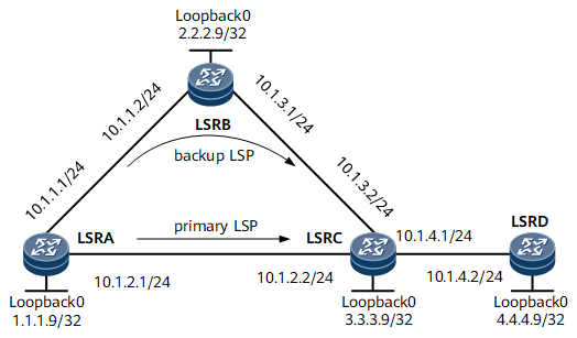
On the network shown in Figure 1, a primary LSP between LSRA and LSRC and a backup LSP over a path LSRA -> LSRB -> LSRC are established. To allow traffic to rapidly switch to the backup LSP if the primary LSP fails, LDP Auto FRR can be configured on LSRA, which minimizes traffic loss.
Device Name |
Interface Name |
IP Address |
|---|---|---|
LSRA |
Loopback0 |
1.1.1.9/32 |
GigabitEthernet0/1/0 |
10.1.1.1/24 |
|
GigabitEthernet0/1/1 |
10.1.2.1/24 |
|
LSRB |
Loopback0 |
2.2.2.9/32 |
GigabitEthernet0/1/0 |
10.1.1.2/24 |
|
GigabitEthernet0/1/1 |
10.1.3.1/24 |
|
LSRC |
Loopback0 |
3.3.3.9/32 |
GigabitEthernet0/1/0 |
10.1.4.1/24 |
|
GigabitEthernet0/1/1 |
10.1.2.2/24 |
|
GigabitEthernet0/1/2 |
10.1.3.2/24 |
|
LSRD |
Loopback0 |
4.4.4.9/32 |
GigabitEthernet0/1/0 |
10.1.4.2/24 |
Configuration Roadmap
The configuration roadmap is as follows:
Assign an IP address and its mask to every interface and configure a loopback interface address as an LSR ID on every node.
Configure IS-IS to advertise the route to each network segment to which each interface is connected and to advertise the host route to each LSR ID.
Enable MPLS and MPLS LDP on each node and its interfaces.
Enable IS-IS Auto FRR on the ingress to protect traffic.
Configure a policy for triggering LDP LSP establishment based on all routes.
Configure a policy for triggering backup LDP LSP establishment on LSRA.
Data Preparation
To complete the configuration, you need the following data:
IP address of every interface on every node shown in Figure 1, IS-IS process ID, and level of each router
Policy for triggering backup LDP LSP establishment
Procedure
- Assign an IP address to each interface.
Assign an IP address and its mask to each physical interface and configure a loopback interface address as an LSR ID on every node shown in Figure 1. For configuration details, see Configuration Files in this section.
- Configure IS-IS to advertise the route to each network segment to which each interface is connected and to advertise the host route to each LSR ID.
# Configure LSRA.
<LSRA> system-view
[~LSRA] isis 1
[*LSRA-isis-1] network-entity 10.0000.0000.0001.00
[*LSRA-isis-1] quit
[*LSRA] interface gigabitethernet 0/1/0
[*LSRA-GigabitEthernet0/1/0] isis enable 1
[*LSRA-GigabitEthernet0/1/0] quit
[*LSRA] interface gigabitethernet 0/1/1
[*LSRA-GigabitEthernet0/1/1] isis enable 1
[*LSRA-GigabitEthernet0/1/1] quit
[*LSRA] interface loopBack 0
[*LSRA-LoopBack0] isis enable 1
[*LSRA-LoopBack0] quit
[*LSRA] commit
# Configure LSRB.
<LSRB> system-view
[~LSRB] isis 1
[*LSRB-isis-1] network-entity 10.0000.0000.0002.00
[*LSRB-isis-1] quit
[*LSRB] interface gigabitethernet 0/1/0
[*LSRB-GigabitEthernet0/1/0] isis enable 1
[*LSRB-GigabitEthernet0/1/0] quit
[*LSRB] interface gigabitethernet 0/1/1
[*LSRB-GigabitEthernet0/1/1] isis enable 1
[*LSRB-GigabitEthernet0/1/1] quit
[*LSRB] interface loopBack 0
[*LSRB-LoopBack0] isis enable 1
[*LSRB-LoopBack0] quit
[*LSRB] commit
# Configure LSRC.
<LSRC> system-view
[~LSRC] isis 1
[*LSRC-isis-1] network-entity 10.0000.0000.0003.00
[*LSRC-isis-1] quit
[*LSRC] interface gigabitethernet 0/1/0
[*LSRC-GigabitEthernet0/1/0] isis enable 1
[*LSRC-GigabitEthernet0/1/0] quit
[*LSRC] interface gigabitethernet 0/1/1
[*LSRC-GigabitEthernet0/1/1] isis enable 1
[*LSRC-GigabitEthernet0/1/1] quit
[*LSRC] interface gigabitethernet 0/1/2
[*LSRC-GigabitEthernet0/1/2] isis enable 1
[*LSRC-GigabitEthernet0/1/2] quit
[*LSRC] interface loopBack 0
[*LSRC-LoopBack0] isis enable 1
[*LSRC-LoopBack0] quit
[*LSRC] commit
# Configure LSRD.
<LSRD> system-view
[~LSRD] isis 1
[*LSRD-isis-1] network-entity 10.0000.0000.0004.00
[*LSRD-isis-1] quit
[*LSRD] interface gigabitethernet 0/1/0
[*LSRD-GigabitEthernet0/1/0] isis enable 1
[*LSRD-GigabitEthernet0/1/0] quit
[*LSRD] interface loopBack 0
[*LSRD-LoopBack0] isis enable 1
[*LSRD-LoopBack0] quit
[*LSRD] commit
- Configure MPLS and MPLS LDP on every node and its interfaces to forward MPLS traffic, and verify LSP information.
# Configure LSRA.
[~LSRA] mpls lsr-id 1.1.1.9
[*LSRA] mpls
[*LSRA-mpls] quit
[*LSRA] mpls ldp
[*LSRA-mpls-ldp] quit
[*LSRA] interface gigabitethernet 0/1/0
[*LSRA-GigabitEthernet0/1/0] mpls
[*LSRA-GigabitEthernet0/1/0] mpls ldp
[*LSRA-GigabitEthernet0/1/0] quit
[*LSRA] interface gigabitethernet 0/1/1
[*LSRA-GigabitEthernet0/1/1] mpls
[*LSRA-GigabitEthernet0/1/1] mpls ldp
[*LSRA-GigabitEthernet0/1/1] quit
[*LSRA] commit
# Configure LSRB.
[~LSRB] mpls lsr-id 2.2.2.9
[*LSRB] mpls
[*LSRB-mpls] quit
[*LSRB] mpls ldp
[*LSRB-mpls-ldp] quit
[*LSRB] interface gigabitethernet 0/1/0
[*LSRB-GigabitEthernet0/1/0] mpls
[*LSRB-GigabitEthernet0/1/0] mpls ldp
[*LSRB-GigabitEthernet0/1/0] quit
[*LSRB] interface gigabitethernet 0/1/1
[*LSRB-GigabitEthernet0/1/1] mpls
[*LSRB-GigabitEthernet0/1/1] mpls ldp
[*LSRB-GigabitEthernet0/1/1] quit
[*LSRB] commit
# Configure LSRC.
[~LSRC] mpls lsr-id 3.3.3.9
[*LSRC] mpls
[*LSRC-mpls] quit
[*LSRC] mpls ldp
[*LSRC-mpls-ldp] quit
[*LSRC] interface gigabitethernet 0/1/0
[*LSRC-GigabitEthernet0/1/0] mpls
[*LSRC-GigabitEthernet0/1/0] mpls ldp
[*LSRC-GigabitEthernet0/1/0] quit
[*LSRC] interface gigabitethernet 0/1/1
[*LSRC-GigabitEthernet0/1/1] mpls
[*LSRC-GigabitEthernet0/1/1] mpls ldp
[*LSRC-GigabitEthernet0/1/1] quit
[*LSRC] interface gigabitethernet 0/1/2
[*LSRC-GigabitEthernet0/1/2] mpls
[*LSRC-GigabitEthernet0/1/2] mpls ldp
[*LSRC-GigabitEthernet0/1/2] quit
[*LSRC] commit
# Configure LSRD.
[~LSRD] mpls lsr-id 4.4.4.9
[*LSRD] mpls
[*LSRD-mpls] quit
[*LSRD] mpls ldp
[*LSRD-mpls-ldp] quit
[*LSRD] interface gigabitethernet 0/1/0
[*LSRD-GigabitEthernet0/1/0] mpls
[*LSRD-GigabitEthernet0/1/0] mpls ldp
[*LSRD-GigabitEthernet0/1/0] quit
[*LSRD] commit
# After completing the preceding configurations, run the display mpls lsp command on LSRA to view information about the established LSP.
[~LSRA] display mpls lsp
Flag after Out IF: (I) - RLFA Iterated LSP, (I*) - Normal and RLFA Iterated LSP
Flag after LDP FRR: (L) - Logic FRR LSP
-------------------------------------------------------------------------------
                 LSP Information: LDP LSP
-------------------------------------------------------------------------------
FEC                In/Out Label    In/Out IF                      Vrf Name
1.1.1.9/32         3/NULL          -/-
2.2.2.9/32         NULL/3          -/GE0/1/0
2.2.2.9/32         1024/3          -/GE0/1/0
3.3.3.9/32         NULL/3          -/GE0/1/1
3.3.3.9/32         1025/3          -/GE0/1/1
4.4.4.9/32         NULL/1026       -/GE0/1/1
4.4.4.9/32         1026/1026       -/GE0/1/1
The command output shows that the host route to an address with a 32-bit mask has been used to establish the LDP LSP. This means that the default policy for triggering LSP establishment has been used.
- Enable IS-IS Auto FRR on LSRA and verify routing information and backup LSP information.
# Enable IS-IS Auto FRR on LSRA.
[~LSRA] isis
[~LSRA-isis-1] frr
[*LSRA-isis-1-frr] loop-free-alternate
[*LSRA-isis-1-frr] quit
[*LSRA-isis-1] quit
[*LSRA] commit
# Display routing information of direct links between LSRA and LSRC and between LSRC and LSRD.
[~LSRA] display ip routing-table 10.1.4.0 verbose
Route Flags: R - relay, D - download to fib, T - to vpn-instance, B - black hole route
------------------------------------------------------------------------------
Routing Table : _public_
Summary Count : 1

Destination: 10.1.4.0/24
     Protocol: ISIS            Process ID: 1
   Preference: 15                    Cost: 20
      NextHop: 10.1.2.2         Neighbour: 0.0.0.0
        State: Active Adv             Age: 00h05m38s
          Tag: 0                 Priority: low
        Label: NULL               QoSInfo: 0x0
   IndirectID: 0x0
 RelayNextHop: 0.0.0.0          Interface: GigabitEthernet0/1/1
     TunnelID: 0x0                  Flags: D
    BkNextHop: 10.1.1.2       BkInterface: GigabitEthernet0/1/0
      BkLabel: NULL           SecTunnelID: 0x0
 BkPETunnelID: 0x0        BkPESecTunnelID: 0x0
 BkIndirectID: 0x0
The command output shows that a backup IS-IS route has been generated after IS-IS Auto FRR was enabled.
# Run the display mpls lsp command on LSRA to view LSP information.
[~LSRA] display mpls lsp
Flag after Out IF: (I) - RLFA Iterated LSP, (I*) - Normal and RLFA Iterated LSP
Flag after LDP FRR: (L) - Logic FRR LSP
-------------------------------------------------------------------------------
                 LSP Information: LDP LSP
-------------------------------------------------------------------------------
FEC                In/Out Label    In/Out IF                      Vrf Name
1.1.1.9/32         3/NULL          -/-
2.2.2.9/32         NULL/3          -/GE0/1/0
2.2.2.9/32         23/3            -/GE0/1/0
   **LDP FRR**     NULL/17         -/GE0/1/1
   **LDP FRR**     23/17           -/GE0/1/1
3.3.3.9/32         NULL/18         -/GE0/1/1
3.3.3.9/32         24/18           -/GE0/1/1
   **LDP FRR**     NULL/18         -/GE0/1/0
   **LDP FRR**     24/18           -/GE0/1/0
4.4.4.9/32         NULL/3          -/GE0/1/1
4.4.4.9/32         25/3            -/GE0/1/1
   **LDP FRR**     NULL/19         -/GE0/1/0
   **LDP FRR**     25/19           -/GE0/1/0
The command output shows that the backup route to an address with a 32-bit mask has been used to establish the backup LSP. This means that the default policy for triggering backup LSP establishment has been used.
- Configure a policy to allow all routes to be used to trigger LDP LSP establishment and view LSP information.
# Run the lsp-trigger command on LSRA to allow all routes to be used to trigger LDP LSP establishment and view LSP information.
[~LSRA] mpls
[~LSRA-mpls] lsp-trigger all
[*LSRA-mpls] quit
[*LSRA] commit
# Run the lsp-trigger command on LSRB to allow all routes to be used to trigger LDP LSP establishment and view LSP information.
[~LSRB] mpls
[~LSRB-mpls] lsp-trigger all
[*LSRB-mpls] quit
[*LSRB] commit
# Run the lsp-trigger command on LSRC to allow all routes to be used to trigger LDP LSP establishment and view LSP information.
[~LSRC] mpls
[~LSRC-mpls] lsp-trigger all
[*LSRC-mpls] quit
[*LSRC] commit
# Run the lsp-trigger command on LSRD to allow all routes to be used to trigger LDP LSP establishment and view LSP information.
[~LSRD] mpls
[~LSRD-mpls] lsp-trigger all
[*LSRD-mpls] quit
[*LSRD] commit
# Run the display mpls lsp command on LSRA to view LSP information.
[~LSRA] display mpls lsp
Flag after Out IF: (I) - RLFA Iterated LSP, (I*) - Normal and RLFA Iterated LSP
Flag after LDP FRR: (L) - Logic FRR LSP
-------------------------------------------------------------------------------
                 LSP Information: LDP LSP
-------------------------------------------------------------------------------
FEC                In/Out Label    In/Out IF                      Vrf Name
1.1.1.9/32         3/NULL          -/-
2.2.2.9/32         NULL/3          -/GE0/1/0
2.2.2.9/32         23/3            -/GE0/1/0
   **LDP FRR**     NULL/17         -/GE0/1/1
   **LDP FRR**     23/17           -/GE0/1/1
3.3.3.9/32         NULL/18         -/GE0/1/1
3.3.3.9/32         24/18           -/GE0/1/1
   **LDP FRR**     NULL/18         -/GE0/1/0
   **LDP FRR**     24/18           -/GE0/1/0
4.4.4.9/32         NULL/3          -/GE0/1/1
4.4.4.9/32         25/3            -/GE0/1/1
   **LDP FRR**     NULL/19         -/GE0/1/0
   **LDP FRR**     25/19           -/GE0/1/0
10.1.1.0/24        3/NULL          -/-
10.1.2.0/24        3/NULL          -/-
10.1.3.0/24        NULL/3          -/GE0/1/0
10.1.3.0/24        28/3            -/GE0/1/0
10.1.3.0/24        NULL/3          -/GE0/1/1
10.1.3.0/24        28/3            -/GE0/1/1
10.1.4.0/24        NULL/3          -/GE0/1/1
10.1.4.0/24        29/3            -/GE0/1/1
The command output shows that routes to addresses with 24-bit masks are used to set up LSPs.
- Configure a policy for triggering backup LSP establishment based all routes.
# Run the auto-frr lsp-trigger command on LSRA to allow LDP to use all backup routes to establish backup LSPs.
[~LSRA] mpls ldp
[~LSRA-mpls-ldp] auto-frr lsp-trigger all
[*LSRA-mpls-ldp] quit
[*LSRA] commit
- Verify the configuration.
# After completing the preceding configurations, run the display mpls lsp command on LSRA to view LSP information.
[~LSRA] display mpls lsp
Flag after Out IF: (I) - RLFA Iterated LSP, (I*) - Normal and RLFA Iterated LSP
Flag after LDP FRR: (L) - Logic FRR LSP
-------------------------------------------------------------------------------
                 LSP Information: LDP LSP
-------------------------------------------------------------------------------
FEC                In/Out Label    In/Out IF                      Vrf Name
1.1.1.9/32         3/NULL          -/-
2.2.2.9/32         NULL/3          -/GE0/1/0
2.2.2.9/32         23/3            -/GE0/1/0
   **LDP FRR**     NULL/17         -/GE0/1/1
   **LDP FRR**     23/17           -/GE0/1/1
3.3.3.9/32         NULL/18         -/GE0/1/1
3.3.3.9/32         24/18           -/GE0/1/1
   **LDP FRR**     NULL/18         -/GE0/1/0
   **LDP FRR**     24/18           -/GE0/1/0
4.4.4.9/32         NULL/3          -/GE0/1/1
4.4.4.9/32         25/3            -/GE0/1/1
   **LDP FRR**     NULL/19         -/GE0/1/0
   **LDP FRR**     25/19           -/GE0/1/0
10.1.1.0/24        3/NULL          -/-
10.1.2.0/24        3/NULL          -/-
10.1.3.0/24        NULL/3          -/GE0/1/0
10.1.3.0/24        28/3            -/GE0/1/0
10.1.3.0/24        NULL/3          -/GE0/1/1
10.1.3.0/24        28/3            -/GE0/1/1
10.1.4.0/24        NULL/3          -/GE0/1/1
10.1.4.0/24        29/3            -/GE0/1/1
   **LDP FRR**     NULL/26         -/GE0/1/0
   **LDP FRR**     29/26           -/GE0/1/0
The command output shows that a backup CR-LSP over a path LSRA -> LSRB -> LSRC has been established for the primary CR-LSP over a path LSRA -> LSRC -> LSRD.
Configuration Files
LSRA configuration file
#
sysname LSRA
#
mpls lsr-id 1.1.1.9
#
mpls
#
mpls ldp
 #
 ipv4-family
  auto-frr lsp-trigger all
#
isis 1
 frr
  loop-free-alternate level-1
  loop-free-alternate level-2
 network-entity 10.0000.0000.0001.00
#
interface GigabitEthernet0/1/0
 undo shutdown
 ip address 10.1.1.1 255.255.255.0
 isis enable 1
 mpls
 mpls ldp
#
interface GigabitEthernet0/1/1
 undo shutdown
 ip address 10.1.2.1 255.255.255.0
 isis enable 1
 mpls
 mpls ldp
#
interface LoopBack0
 ip address 1.1.1.9 255.255.255.255
 isis enable 1
#
return
LSRB configuration file
#
sysname LSRB
#
mpls lsr-id 2.2.2.9
#
mpls
 lsp-trigger all
#
mpls ldp
 #
 ipv4-family
#
isis 1
 network-entity 10.0000.0000.0002.00
#
interface GigabitEthernet0/1/0
 undo shutdown
 ip address 10.1.1.2 255.255.255.0
 isis enable 1
 mpls
 mpls ldp
#
interface GigabitEthernet0/1/1
 undo shutdown
 ip address 10.1.3.1 255.255.255.0
 isis enable 1
 mpls
 mpls ldp
#
interface LoopBack0
 ip address 2.2.2.9 255.255.255.255
 isis enable 1
#
return
LSRC configuration file
#
sysname LSRC
#
mpls lsr-id 3.3.3.9
#
mpls
 lsp-trigger all
#
mpls ldp
 #
 ipv4-family
#
isis 1
 network-entity 10.0000.0000.0003.00
#
interface GigabitEthernet0/1/0
 undo shutdown
 ip address 10.1.4.1 255.255.255.0
 isis enable 1
 mpls
 mpls ldp
#
interface GigabitEthernet0/1/1
 undo shutdown
 ip address 10.1.2.2 255.255.255.0
 isis enable 1
 mpls
 mpls ldp
#
interface GigabitEthernet0/1/2
 undo shutdown
 ip address 10.1.3.2 255.255.255.0
 isis enable 1
 mpls
 mpls ldp
#
interface LoopBack0
 ip address 3.3.3.9 255.255.255.255
 isis enable 1
#
return
LSRD configuration file
#
 sysname LSRD
#
mpls lsr-id 4.4.4.9
#
mpls
#
mpls ldp
 #
 ipv4-family
#
isis 1
 network-entity 10.0000.0000.0004.00
#
interface GigabitEthernet0/1/0
 undo shutdown
 ip address 10.1.4.2 255.255.255.0
 isis enable 1
 mpls
 mpls ldp
#
interface LoopBack0
 ip address 4.4.4.9 255.255.255.255
 isis enable 1
#
return