Example for Configuring Dynamic BFD to Monitor LDP LSPs
This section provides an example for configuring dynamic BFD to monitor LDP LSPs.
Networking Requirements
The proliferation of MPLS LDP applications drives the increasing demand for network reliability. To meet the reliability requirement, BFD for LDP can be used. BFD for LDP is a detection mechanism that can rapidly detect faults and trigger a primary/backup LSP switchover. The BFD for LDP function and LDP FRR function are used together on an MPLS LDP network.
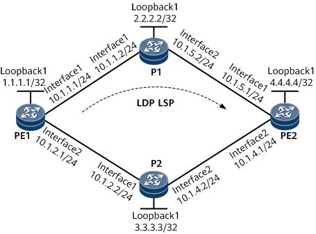
On the network shown in Figure 1, PE1, P1, P2, and PE2 are in the same MPLS domain. PE1 and PE2 establish primary and backup LDP LSPs. To monitor the LDP LSPs, configure dynamic BFD.

Configuration Notes
When configuring dynamic BFD to monitor LDP LSPs, note the following:
Each LSR must have route entries that exactly match FECs for the LSPs to be established.
LDP by default uses 32-bit host routes to establish LSPs.
LDP can use all IGP routes except BGP routes to establish LSPs.
Configuration Roadmap
The configuration roadmap is as follows:
Assign an IP address to each interface of each LSR according to Figure 1.
Configure OSPF to implement network layer connectivity and set interface cost values so that the LSP along the path PE1 -> P1 -> PE2 functions as the primary LSP, and the LSP along the path PE1 -> P2 -> PE2 functions as the backup LSP.
Enable LSRs to use all IGP routes to establish LDP LSPs.
Configure OSPF FRR and LDP Auto FRR to create a backup LSP between PE1 and PE2.
Configure dynamic BFD for LDP to use FEC lists to create BFD sessions.
Data Preparation
To complete the configuration, you need the following data:
LSR ID (equal to a loopback interface address) of each node and IP address of each interface shown in Figure 1
OSPF process ID (1) and area ID (0)
Policy (using all IGP routes) for establishing LDP LSPs
FEC list names (11 and 12)
Minimum interval (100 ms) at which BFD packets are sent, minimum interval (600 ms) at which BFD packets are received, and detection multiplier (4)
Procedure
- Assign an IP address to each interface.
Assign an IP address to each interface according to Figure 1 and create a loopback interface on each node. For configuration details, see Configuration Files in this section.
- Configure OSPF.
Configure OSPF on each node to implement network layer connectivity. For configuration details, see Configuration Files in this section.
- Configure LDP LSPs.
Configure MPLS LDP on each node and enable the nodes to use all IGP routes to establish LDP LSPs. For configuration details, see Configuration Files in this section.
- Configure OSPF FRR and LDP Auto FRR on each node.
# Configure PE1.
[~PE1] ospf 1
[~PE1-ospf-1] frr
[*PE1-ospf-1-frr] loop-free-alternate
[*PE1-ospf-1-frr] commit
[~PE1-ospf-1-frr] quit
[~PE1-ospf-1] quit
[~PE1] mpls ldp
[~PE1-mpls-ldp] auto-frr lsp-trigger all
[*PE1-mpls-ldp] commit
[~PE1-mpls-ldp] quit
# Configure PE2.
[~PE2] ospf 1
[~PE2-ospf-1] frr
[*PE2-ospf-1-frr] loop-free-alternate
[*PE2-ospf-1-frr] commit
[~PE2-ospf-1-frr] quit
[~PE2-ospf-1] quit
[~PE2] mpls ldp
[~PE2-mpls-ldp] auto-frr lsp-trigger all
[*PE2-mpls-ldp] commit
[~PE2-mpls-ldp] quit
- Configure dynamic BFD sessions to monitor LDP LSPs.
# Enable BFD, specify a FEC list used to establish a BFD session, and set BFD parameters on PE1.
[~PE1] bfd
[*PE1-bfd] mpls-passive
[*PE1-bfd] commit
[~PE1-bfd] quit
[~PE1] fec-list l1
[*PE1-fec-list-l1] fec-node 4.4.4.4
[*PE1-fec-list-l1] commit
[~PE1-fec-list-l1] quit
[~PE1] mpls
[~PE1-mpls] mpls bfd enable
[*PE1-mpls] mpls bfd-trigger fec-list l1
[*PE1-mpls] mpls bfd min-tx-interval 100 min-rx-interval 600 detect-multiplier 4
[*PE1-mpls] commit
[~PE1-mpls] quit
# Enable BFD, specify a FEC list used to establish a BFD session, and set BFD parameters on PE2.
[~PE2] bfd
[*PE2-bfd] mpls-passive
[*PE2-bfd] commit
[~PE2-bfd] quit
[~PE2] fec-list l2
[*PE2-fec-list-l2] fec-node 1.1.1.1
[*PE2-fec-list-l2] commit
[~PE2-fec-list-l2] quit
[~PE2] mpls
[~PE2-mpls] mpls bfd enable
[*PE2-mpls] mpls bfd-trigger fec-list l2
[*PE2-mpls] mpls bfd min-tx-interval 100 min-rx-interval 600 detect-multiplier 4
[*PE2-mpls] commit
[~PE2-mpls] quit
- Verify the configuration.
# Run the display bfd session all verbose command to view the dynamic BFD session status on PE1. The BFD session status is Up.
[~PE1] display bfd session all verbose
(w): State in WTR
(*): State is invalid
--------------------------------------------------------------------------------
  State : Up                    Name : dyn_16388
--------------------------------------------------------------------------------
  Local Discriminator    : 16388            Remote Discriminator   : 16386
  Session Detect Mode    : Asynchronous Mode Without Echo Function
  BFD Bind Type          : LDP_LSP
  Bind Session Type      : Dynamic
  Bind Peer IP Address   : 4.4.4.4
  NextHop Ip Address     : 10.1.1.2
  Bind Interface         : GigabitEthernet0/1/0
  Tunnel ID              : -
  FSM Board Id           : 3                TOS-EXP                : 7
  Min Tx Interval (ms)   : 600              Min Rx Interval (ms)   : 100
  Actual Tx Interval (ms): 600              Actual Rx Interval (ms): 100
  Local Detect Multi     : 4                Detect Interval (ms)   : 300
  Echo Passive           : Disable          Acl Number             : -
  Destination Port       : 3784             TTL                    : 1
  Proc Interface Status  : Disable          Process PST            : Enable
  WTR Interval (ms)      : -                Config PST             : Enable
  Active Multi           : 3
  Last Local Diagnostic  : No Diagnostic
  Bind Application       : LDP
  Session TX TmrID       : -                Session Detect TmrID   : -
  Session Init TmrID     : -                Session WTR TmrID      : -
  Session Echo Tx TmrID  : -
  Session Description    : -
--------------------------------------------------------------------------------

--------------------------------------------------------------------------------
  (Multi Hop) State : Up                    Name : dyn_16390
--------------------------------------------------------------------------------
  Local Discriminator    : 16390            Remote Discriminator   : 16387
  Session Detect Mode    : Asynchronous Mode Without Echo Function
  BFD Bind Type          : Peer IP Address
  Bind Session Type      : Entire_Dynamic
  Bind Peer IP Address   : 4.4.4.4
  Bind Interface         : -
  Track Interface        : -
  Bind Source IP Address : 1.1.1.1
  FSM Board Id           : 3                TOS-EXP                : 7
  Min Tx Interval (ms)   : 10               Min Rx Interval (ms)   : 10
  Actual Tx Interval (ms): 100              Actual Rx Interval (ms): 600
  Local Detect Multi     : 3                Detect Interval (ms)   : 2400
  Echo Passive           : Disable          Acl Number             : -
  Destination Port       : 3784             TTL                    : 253
  Proc Interface Status  : Disable          Process PST            : Disable
  WTR Interval (ms)      : -                Config PST             : Disable
  Active Multi           : 4
  Last Local Diagnostic  : No Diagnostic
  Bind Application       : No Application Bind
  Session TX TmrID       : -                Session Detect TmrID   : -
  Session Init TmrID     : -                Session WTR TmrID      : -
  Session Echo Tx TmrID  : -
  Session Description    : -
--------------------------------------------------------------------------------

    Total UP/DOWN Session Number : 2/0
# Run the display bfd session passive-dynamic verbose command to view the passively created BFD session status on PE2. The BFD session status is Up. The BFD Bind Type value is Peer IP Address, which indicates that PE2 sends BFD packets over IP routes.
[~PE2] display bfd session passive-dynamic verbose
(w): State in WTR
(*): State is invalid
--------------------------------------------------------------------------------
  (Multi Hop) State : Up                    Name : dyn_16386
--------------------------------------------------------------------------------
  Local Discriminator    : 16386            Remote Discriminator   : 16388
  Session Detect Mode    : Asynchronous Mode Without Echo Function
  BFD Bind Type          : Peer IP Address
  Bind Session Type      : Entire_Dynamic
  Bind Peer IP Address   : 1.1.1.1
  Bind Interface         : -
  Track Interface        : -
  Bind Source IP Address : 4.4.4.4
  FSM Board Id           : 3                TOS-EXP                : 7
  Min Tx Interval (ms)   : 10               Min Rx Interval (ms)   : 10
  Actual Tx Interval (ms): 100              Actual Rx Interval (ms): 600
  Local Detect Multi     : 3                Detect Interval (ms)   : 2400
  Echo Passive           : Disable          Acl Number             : -
  Destination Port       : 3784             TTL                    : 253
  Proc Interface Status  : Disable          Process PST            : Disable
  WTR Interval (ms)      : -                Config PST             : Disable
  Active Multi           : 4
  Last Local Diagnostic  : No Diagnostic
  Bind Application       : No Application Bind
  Session TX TmrID       : -                Session Detect TmrID   : -
  Session Init TmrID     : -                Session WTR TmrID      : -
  Session Echo Tx TmrID  : -
  Session Description    : -
--------------------------------------------------------------------------------

    Total UP/DOWN Session Number : 1/0
Configuration Files
PE1 configuration file
#
sysname PE1
#
bfd
 mpls-passive
#
mpls lsr-id 1.1.1.1
#
mpls
 lsp-trigger all
 mpls bfd enable
 mpls bfd-trigger fec-list l1
 mpls bfd min-tx-interval 600 min-rx-interval 100 detect-multiplier 4
#
fec-list l1
 fec-node 4.4.4.4
#
mpls ldp
 #
 ipv4-family
  auto-frr lsp-trigger all
#
interface GigabitEthernet0/1/0
 undo shutdown
 ip address 10.1.1.1 255.255.255.0
 mpls
 mpls ldp
#
interface GigabitEthernet0/1/1
 undo shutdown
 ip address 10.1.2.1 255.255.255.0
 ospf cost 2
 mpls
 mpls ldp
#
interface LoopBack1
 ip address 1.1.1.1 255.255.255.255
#
ospf 1
 frr
  loop-free-alternate
 area 0.0.0.0
  network 1.1.1.1 0.0.0.0
  network 10.1.1.0 0.0.0.255
  network 10.1.2.0 0.0.0.255
#
return
PE2 configuration file
#
sysname PE2
#
bfd
 mpls-passive
#
mpls lsr-id 4.4.4.4
#
mpls
 lsp-trigger all
 mpls bfd enable
 mpls bfd-trigger fec-list l2
 mpls bfd min-tx-interval 600 min-rx-interval 100 detect-multiplier 4
#
fec-list l2
 fec-node 1.1.1.1
#
mpls ldp
 #
 ipv4-family
  auto-frr lsp-trigger all
#
interface GigabitEthernet0/1/0
 undo shutdown
 ip address 10.1.5.1 255.255.255.0
 mpls
 mpls ldp
#
interface GigabitEthernet0/1/1
 undo shutdown
 ip address 10.1.4.1 255.255.255.0
 ospf cost 2
 mpls
 mpls ldp
#
interface LoopBack1
 ip address 4.4.4.4 255.255.255.255
#
ospf 1
 frr
  loop-free-alternate
 area 0.0.0.0
  network 4.4.4.4 0.0.0.0
  network 10.1.4.0 0.0.0.255
  network 10.1.5.0 0.0.0.255
#
return
P1 configuration file
#
sysname P1
#
mpls lsr-id 2.2.2.2
#
mpls
 lsp-trigger all
#
mpls ldp
 #
 ipv4-family
#
interface GigabitEthernet0/1/0
 undo shutdown
 ip address 10.1.1.2 255.255.255.0
 mpls
 mpls ldp
#
interface GigabitEthernet0/1/1
 undo shutdown
 ip address 10.1.5.2 255.255.255.0
 mpls
 mpls ldp
#
interface LoopBack1
 ip address 2.2.2.2 255.255.255.255
#
ospf 1
 area 0.0.0.0
  network 2.2.2.2 0.0.0.0
  network 10.1.1.0 0.0.0.255
  network 10.1.5.0 0.0.0.255
#
return
P2 configuration file
#
sysname P2
#
mpls lsr-id 3.3.3.3
#
mpls
 lsp-trigger all
#
mpls ldp
 #
 ipv4-family
#
interface GigabitEthernet0/1/0
 undo shutdown
 ip address 10.1.2.2 255.255.255.0
 mpls
 mpls ldp
#
interface GigabitEthernet0/1/1
 undo shutdown
 ip address 10.1.4.2 255.255.255.0
 mpls
 mpls ldp
#
interface LoopBack1
 ip address 3.3.3.3 255.255.255.255
#
ospf 1
 area 0.0.0.0
  network 3.3.3.3 0.0.0.0
  network 10.1.2.0 0.0.0.255
  network 10.1.4.0 0.0.0.255
#
return