Example for Configuring the BGP SoO Attribute
By configuring the BGP SoO attribute, you can prevent routes sent from a VPN site from returning to the same site after these routes travel across the backbone network. This avoids routing loops in the VPN site.
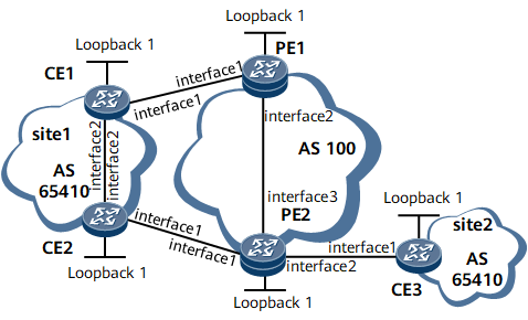
Networking Requirements
If multiple CEs in a VPN site access different PEs, VPN routes sent from CEs to PEs may return to this VPN site after traveling across the backbone network. This may cause routing loops in the VPN site.
On the network shown in Figure 1, CE1 and CE2 belong to Site1; CE2 and CE3 access PE2; Site1 and Site2 have the same AS number. EBGP runs between PEs and CEs. PE1 sends the routes received from CE1 to PE2 through MP-IBGP, and PE2 then sends the received routes to CE2 and CE3. CE2, however, has learned these routes through other protocol in the VPN site. As a result, a routing loop may occur in the VPN site.
After you configure the BGP SoO attribute, PE2 checks the SoO attribute carried in the routes to be sent to CE2. If PE2 finds that this SoO attribute is the same as the locally configured SoO attribute, PE2 refuses to send these routes to CE2. This avoids routing loops in Site1. PE2 can still send these routes to CE3.

Interfaces 1 through 3 in this example represent GE 0/1/0, GE 0/1/8, and GE 0/1/16, respectively.
Device Name |
Interface |
IP Address |
CE1 |
Loopback 1 |
11.11.11.11/32 |
CE1 |
GE 0/1/0 |
192.168.1.2/30 |
CE1 |
GE 0/1/8 |
192.168.4.1/30 |
PE1 |
Loopback 1 |
1.1.1.1/32 |
PE1 |
GE 0/1/0 |
192.168.1.1/30 |
PE1 |
GE 0/1/8 |
192.168.5.1/30 |
PE2 |
Loopback 1 |
2.2.2.2/32 |
PE2 |
GE 0/1/0 |
192.168.2.1/30 |
PE2 |
GE 0/1/8 |
192.168.3.1/30 |
PE2 |
GE 0/1/16 |
192.168.5.2/30 |
CE2 |
Loopback 1 |
22.22.22.22/32 |
CE2 |
GE 0/1/0 |
192.168.2.2/30 |
CE2 |
GE 0/1/8 |
192.168.4.2/30 |
CE3 |
Loopback 1 |
33.33.33.33/32 |
CE3 |
GE 0/1/0 |
192.168.3.2/30 |
Configuration Roadmap
The configuration roadmap is as follows:
Configure an IP address for each interface and an IGP on the backbone network so that PEs can communicate.
Enable MPLS and MPLS LDP on the backbone network so that LDP LSPs can be established between PEs.
Establish an MP-IBGP peer relationship between PEs.
Configure a VPN instance on each PE and bind the interface that connects a PE to a CE to the VPN instance on that PE.
Establish EBGP peer relationships between PEs and CEs and enable AS number substitution on PEs.
Configure the BGP SoO attribute on PEs for CEs.
Data Preparation
To complete the configuration, you need the following data:
MPLS LSR IDs of PEs
Names of the VPN instances created on PE1 and PE2, RDs, and VPN targets of the VPN instance IPv4 address family
Numbers of the ASs where PEs and CEs reside
Value of the BGP SoO attribute on PEs
Procedure
- Configure an IP address for each interface and an IGP on the backbone network so that the PEs can learn routes to each other's loopback interface.
This example uses OSPF as the IGP. For configuration details, see Configuration Files in this section.
After completing the configurations, run the display ip routing-table command on PEs. The command output shows that the PEs have learned the routes to each other's loopback interface.
The following example uses the command output on PE1.
<PE1> display ip routing-table
Route Flags: R - relay, D - download to fib, T - to vpn-instance, B - black hole route
------------------------------------------------------------------------------
Routing Table: _public_
         Destinations : 9        Routes : 9

Destination/Mask    Proto   Pre  Cost      Flags NextHop         Interface

        1.1.1.1/32  Direct  0    0           D   127.0.0.1       InLoopBack0
        2.2.2.2/32  OSPF    10   1562        D   192.168.5.2      GigabitEthernet0/1/16
      192.168.5.0/30  Direct  0    0         D   192.168.5.1      GigabitEthernet0/1/16
      192.168.5.1/32  Direct  0    0         D   127.0.0.1        GigabitEthernet0/1/16
    192.168.5.255/32  Direct  0    0         D   127.0.0.1        GigabitEthernet0/1/16
      127.0.0.0/8   Direct  0    0           D   127.0.0.1       InLoopBack0
      127.0.0.1/32  Direct  0    0           D   127.0.0.1       InLoopBack0
127.255.255.255/32  Direct  0    0           D   127.0.0.1       InLoopBack0
255.255.255.255/32  Direct  0    0           D   127.0.0.1       InLoopBack0
- Enable MPLS and MPLS LDP on the backbone network so that LDP LSPs can be established between PEs.
You need to enable MPLS and MPLS LDP on the PEs in the system view and interface view.
# Configure PE1.
[*PE1] mpls lsr-id 1.1.1.1
[*PE1] mpls
[*PE1-mpls] quit
[*PE1] mpls ldp
[*PE1-mpls-ldp] quit
[*PE1] interface gigabitethernet0/1/16
[*PE1-GigabitEthernet0/1/16] mpls
[*PE1-GigabitEthernet0/1/16] mpls ldp
[*PE1-GigabitEthernet0/1/16] quit
[*PE1] commit
Repeat this step for PE2. For configuration details, see Configuration Files in this section.
After completing the configurations, run the display mpls ldp lsp command on PEs. The command output shows information about the labels assigned to the routes to loopback interfaces on the other PEs. The following example uses the command output on PE1.
<PE1> display mpls ldp lsp

 LDP LSP Information
 -------------------------------------------------------------------------------
 DestAddress/Mask   In/OutLabel    UpstreamPeer    NextHop         OutInterface
 -------------------------------------------------------------------------------
 1.1.1.1/32         3/NULL         2.2.2.2         127.0.0.1       InLoop0
*1.1.1.1/32         Liberal/1024                   DS/2.2.2.2
 2.2.2.2/32         NULL/3         -               192.168.5.2     GE0/1/16
 2.2.2.2/32         1024/3         2.2.2.2         192.168.5.2     GE0/1/16
 -------------------------------------------------------------------------------
 TOTAL: 3 Normal LSP(s) Found.
 TOTAL: 1 Liberal LSP(s) Found.
 TOTAL: 0 Frr LSP(s) Found.
An asterisk (*) before an LSP means the LSP is not established
 An asterisk (*) before a Label means the USCB or DSCB is stale
 An asterisk (*) before an UpstreamPeer means the session is stale
 An asterisk (*) before a DS means the session is stale
 An asterisk (*) before a NextHop means the LSP is FRR LSP
- Establish an MP-IBGP peer relationship between PEs.
# Configure PE1.
[*PE1] bgp 100
[*PE1-bgp] peer 2.2.2.2 as-number 100
[*PE1-bgp] peer 2.2.2.2 connect-interface loopback1
[*PE1-bgp] ipv4-family vpnv4
[*PE1-bgp-af-vpnv4] peer 2.2.2.2 enable
[*PE1-bgp-af-vpnv4] quit
[*PE1-bgp] quit
[*PE1] commit
Repeat this step for PE2. For configuration details, see Configuration Files in this section.
After completing the configurations, run the display bgp peer or display bgp vpnv4 all peer command on PEs. The command output shows that BGP peer relationships have been established between PEs. The following example uses the command output on PE1.
<PE1> display bgp peer

 BGP local router ID : 192.168.5.1
 Local AS number : 100
 Total number of peers : 1                 Peers in established state : 1

  Peer            V          AS  MsgRcvd  MsgSent  OutQ  Up/Down State       PrefRcv

  2.2.2.2         4         100      187      186     0 02:44:06 Established       1
- Configure an IPv4-address-family-supporting VPN instance on each PE and bind the interface that connects a PE to a CE to the VPN instance on that PE.
# Configure PE1.
[*PE1] ip vpn-instance vpna
[*PE1-vpn-instance-vpna] ipv4-family
[*PE1-vpn-instance-vpna-af-ipv4] route-distinguisher 100:1
[*PE1-vpn-instance-vpna-af-ipv4] vpn-target 100:100
[*PE1-vpn-instance-vpna-af-ipv4] quit
[*PE1-vpn-instance-vpna] quit
[*PE1] interface gigabitethernet0/1/0
[*PE1-GigabitEthernet0/1/0] ip binding vpn-instance vpna
[*PE1-GigabitEthernet0/1/0] ip address 192.168.1.1 30
[*PE1-GigabitEthernet0/1/0] quit
[*PE1] commit
# Configure PE2.
[*PE2] ip vpn-instance vpna
[*PE2-vpn-instance-vpna] ipv4-family
[*PE2-vpn-instance-vpna-af-ipv4] route-distinguisher 100:2
[*PE2-vpn-instance-vpna-af-ipv4] vpn-target 100:100
[*PE2-vpn-instance-vpna-af-ipv4] quit
[*PE2-vpn-instance-vpna] quit
[*PE2] interface gigabitethernet0/1/0
[*PE2-GigabitEthernet0/1/0] ip binding vpn-instance vpna
[*PE2-GigabitEthernet0/1/0] ip address 192.168.2.1 30
[*PE2-GigabitEthernet0/1/0] quit
[*PE2] interface gigabitethernet0/1/8
[*PE2-GigabitEthernet0/1/8] ip binding vpn-instance vpna
[*PE2-GigabitEthernet0/1/8] ip address 192.168.3.1 30
[*PE2-GigabitEthernet0/1/8] quit
[*PE2] commit
After completing the configurations, run the display ip vpn-instance command on PEs to check VPN instance configurations.
- Establish EBGP peer relationships between PEs and CEs, enable AS number substitution on PEs, and configure PEs to import routes from CEs.
In this configuration example, the two VPN sites have the same AS number. Therefore, AS number substitution needs to be enabled on PE1 and PE2.
# Configure PE1.
[*PE1] bgp 100
[*PE1-bgp] ipv4-family vpn-instance vpna
[*PE1-bgp-vpna] peer 192.168.1.2 as-number 65410
[*PE1-bgp-vpna] peer 192.168.1.2 substitute-as
[*PE1-bgp-vpna] import-route direct
[*PE1-bgp-vpna] quit
[*PE1-bgp] quit
[*PE1] commit
# Configure CE1.
[*CE1] bgp 65410
[*CE1-bgp] peer 192.168.1.1 as-number 100
[*CE1-bgp] network 11.11.11.11 32
[*CE1-bgp] network 192.168.4.0 30
[*CE1-bgp] quit
[*CE1] commit
# Configure PE2.
[*PE2] bgp 100
[*PE2-bgp] ipv4-family vpn-instance vpna
[*PE2-bgp-vpna] peer 192.168.2.2 as-number 65410
[*PE2-bgp-vpna] peer 192.168.3.2 as-number 65410
[*PE2-bgp-vpna] peer 192.168.2.2 substitute-as
[*PE2-bgp-vpna] peer 192.168.3.2 substitute-as
[*PE2-bgp-vpna] import-route direct
[*PE2-bgp-vpna] quit
[*PE2-bgp] quit
[*PE2] commit
# Configure CE2.
[*CE2] bgp 65410
[*CE2-bgp] peer 192.168.2.1 as-number 100
[*CE2-bgp] network 22.22.22.22 32
[*CE2-bgp] network 192.168.4.0 30
[*CE2-bgp] quit
[*CE2] commit
# Configure CE3.
[*CE3] bgp 65410
[*CE3-bgp] peer 192.168.3.1 as-number 100
[*CE3-bgp] network 33.33.33.33 32
[*CE3-bgp] quit
[*CE3] commit
After completing the configurations, run the display bgp vpnv4 vpn-instance peer command on PEs. The command output shows that the status of EBGP peer relationships between PEs and CEs is Established. This indicates that EBGP peer relationships have been established between PEs and CEs. The following example uses the command output on PE1.
<PE1> display bgp vpnv4 vpn-instance vpna peer

 BGP local router ID : 192.168.5.1
 Local AS number : 100

 VPN-Instance vpna, router ID 192.168.5.1:
 Total number of peers : 1                 Peers in established state : 1

  Peer            V          AS  MsgRcvd  MsgSent  OutQ  Up/Down    State       PrefRcv

  192.168.1.2        4       65410      224      231     0 03:02:12 Established     1
Run the display bgp vpnv4 routing-table command on PEs. The command output shows information about the routes sent from the PEs to CEs. The following example uses the routes sent from PE2 to CE2.
<PE2> display bgp vpnv4 vpn-instance vpna routing-table peer 192.168.2.2 advertised-routes

 VPN-Instance vpna, router ID 2.2.2.2:

 BGP Local router ID is 2.2.2.2
 Status codes: * - valid, > - best, d - damped, x - best external, a - add path,
               h - history,  i - internal, s - suppressed, S - Stale
               Origin : i - IGP, e - EGP, ? - incomplete
 RPKI validation codes: V - valid, I - invalid, N - not-found

 Total Number of Routes: 7
      Network            NextHop        MED        LocPrf    PrefVal Path/Ogn

 *>i  11.11.11.11/32     1.1.1.1         0          100        0      65410i
 *>   22.22.22.22/32     192.168.2.2     0                     0      65410i
 *>   33.33.33.33/32     192.168.3.2     0                     0      65410i
 *>i  192.168.1.0/30     1.1.1.1         0          100        0      ?
 *>   192.168.2.0/30     0.0.0.0         0                     0      ?
 *>   192.168.3.0/30     0.0.0.0         0                     0      ?
 *>   192.168.4.0/30     192.168.2.2     0                     0      65410i
- Configure the BGP SoO attribute on PEs.
Because CE1 and CE2 reside in the same site, the same BGP SoO attribute needs to be configured on PE1 and PE2 for CE1 and CE2 respectively. Because PE2 accesses two VPN sites, different SoO attributes need to be configured on PE2 for different CEs.
# Configure PE1.
[*PE1] bgp 100
[*PE1-bgp] ipv4-family vpn-instance vpna
[*PE1-bgp-vpna] peer 192.168.1.2 soo 100:101
[*PE1-bgp-vpna] quit
[*PE1-bgp] quit
[*PE1] commit
# Configure PE2.
[*PE2] bgp 100
[*PE2-bgp] ipv4-family vpn-instance vpna
[*PE2-bgp-vpna] peer 192.168.2.2 soo 100:101
[*PE2-bgp-vpna] peer 192.168.3.2 soo 100:102
[*PE2-bgp-vpna] quit
[*PE2-bgp] quit
[*PE2] commit
- Verify the configuration.
After completing the configurations, run the display bgp vpnv4 routing-table command on PE2 again. The command output shows that PE2 does not send any VPN route to CE2 and the routes sent from PE2 to CE3 remain unchanged.
<PE2> display bgp vpnv4 vpn-instance vpna routing-table peer 192.168.3.2 advertised-routes

 VPN-Instance vpna, router ID 2.2.2.2:

 BGP Local router ID is 2.2.2.2
 Status codes: * - valid, > - best, d - damped, x - best external, a - add path,
               h - history,  i - internal, s - suppressed, S - Stale
               Origin : i - IGP, e - EGP, ? - incomplete
 RPKI validation codes: V - valid, I - invalid, N - not-found

 Total Number of Routes: 5
      Network            NextHop        MED        LocPrf    PrefVal Path/Ogn

 *>   22.22.22.22/32     192.168.2.2     0                     0      65410i
 *>   33.33.33.33/32     192.168.3.2     0                     0      65410i
 *>   192.168.2.0/30     0.0.0.0         0                     0      ?
 *>   192.168.3.0/30     0.0.0.0         0                     0      ?
 *>   192.168.4.0/30     192.168.2.2     0                     0      65410i
Run the display bgp vpnv4 routing-table command on PE2. The command output shows information about the SoO attribute carried in the routes sent from PE2 to CE3.
<PE2> display bgp vpnv4 vpn-instance vpna routing-table 11.11.11.11 32

 BGP local router ID : 2.2.2.2
 Local AS number : 100

 VPN-Instance vpna, router ID 2.2.2.2:
 Paths:   1 available, 1 best, 1 select
 BGP routing table entry information of 11.11.11.11/32:
 Label information (Received/Applied): 1028/NULL
 From: 1.1.1.1 (192.168.5.1)
 Route Duration: 00h11m12s
 Relay Tunnel Out-Interface: GigabitEthernet0/1/16
 Relay token: 0x800001
 Original nexthop: 1.1.1.1
 Qos information : 0x0
 Ext-Community:RT <100 : 100>, SoO <100 : 101>
 AS-path 65410, origin igp, MED 0, localpref 100, pref-val 0, valid, internal, b
est, select, active, pre 255
 Advertised to such 2 peers:
 Update-Group 0 :
    192.168.3.2
The preceding command output shows that after the BGP SoO attribute is configured, the VPN routes received from CEs carry the SoO attribute, and PE2 does not send any route to CE2. This indicates that the configuration of the BGP SoO attribute has taken effect.
Configuration Files
- CE1 configuration file
 sysname CE1
#
interface GigabitEthernet0/1/0
 undo shutdown
 ip address 192.168.1.2 255.255.255.252
#
interface GigabitEthernet0/1/8
 undo shutdown
 ip address 192.168.4.1 255.255.255.252
#
interface LoopBack1
 ip address 11.11.11.11 255.255.255.255
#
bgp 65410
 peer 192.168.1.1 as-number 100
 #
 ipv4-family unicast
  undo synchronization
  network 11.11.11.11 255.255.255.255
  network 192.168.4.0 255.255.255.252
  peer 192.168.1.1 enable
#
return
- CE2 configuration file
#
 sysname CE2
#
interface GigabitEthernet0/1/0
 undo shutdown
 ip address 192.168.2.2 255.255.255.252
#
interface GigabitEthernet0/1/8
 undo shutdown
 ip address 192.168.4.2 255.255.255.252
#
interface LoopBack1
 ip address 22.22.22.22 255.255.255.255
#
bgp 65410
 peer 192.168.2.1 as-number 100
 #
 ipv4-family unicast
  undo synchronization
  network 22.22.22.22 255.255.255.255
  network 192.168.4.0 255.255.255.252
  peer 192.168.2.1 enable
#
return
- PE1 configuration file
#
 sysname PE1
#
ip vpn-instance vpna
 ipv4-family
  route-distinguisher 100:1
  apply-label per-instance
  vpn-target 100:100 export-extcommunity
  vpn-target 100:100 import-extcommunity
#
mpls lsr-id 1.1.1.1
#
mpls
#
mpls ldp
#
interface GigabitEthernet0/1/0
 undo shutdown
 ip binding vpn-instance vpna
 ip address 192.168.1.1 255.255.255.252
#
interface GigabitEthernet0/1/16
 undo shutdown
 ip address 192.168.5.1 255.255.255.252
 mpls
 mpls ldp
#
interface LoopBack1
 ip address 1.1.1.1 255.255.255.255
#
bgp 100
 peer 2.2.2.2 as-number 100
 peer 2.2.2.2 connect-interface LoopBack1
 #
 ipv4-family unicast
  undo synchronization
  peer 2.2.2.2 enable
 #
 ipv4-family vpnv4
  policy vpn-target
  peer 2.2.2.2 enable
 #
 ipv4-family vpn-instance vpna
  import-route direct
  peer 192.168.1.2 as-number 65410
  peer 192.168.1.2 substitute-as
  peer 192.168.1.2 soo 100:101
#
ospf 1
 area 0.0.0.0
  network 1.1.1.1 0.0.0.0
  network 192.168.5.0 0.0.0.3
#
return
- PE2 configuration file
#
 sysname PE2
#
ip vpn-instance vpna
 ipv4-family
  route-distinguisher 100:2
  apply-label per-instance
  vpn-target 100:100 export-extcommunity
  vpn-target 100:100 import-extcommunity
#
mpls lsr-id 2.2.2.2
#
mpls
#
mpls ldp
#
interface GigabitEthernet0/1/0
 undo shutdown
 ip binding vpn-instance vpna
 ip address 192.168.2.1 255.255.255.252
#
interface GigabitEthernet0/1/8
 undo shutdown
 ip binding vpn-instance vpna
 ip address 192.168.3.1 255.255.255.252
#
interface GigabitEthernet0/1/16
 undo shutdown
 ip address 192.168.5.2 255.255.255.252
 mpls
 mpls ldp
#
interface LoopBack1
 ip address 2.2.2.2 255.255.255.255
#
bgp 100
 peer 1.1.1.1 as-number 100
 peer 1.1.1.1 connect-interface LoopBack1
 #
 ipv4-family unicast
  undo synchronization
  peer 1.1.1.1 enable
 #
 ipv4-family vpnv4
  policy vpn-target
  peer 1.1.1.1 enable
 #
 ipv4-family vpn-instance vpna
  import-route direct
  peer 192.168.2.2 as-number 65410
  peer 192.168.2.2 substitute-as
  peer 192.168.2.2 soo 100:101
  peer 192.168.3.2 as-number 65410
  peer 192.168.3.2 substitute-as
  peer 192.168.3.2 soo 100:102
#
ospf 1
 area 0.0.0.0
  network 2.2.2.2 0.0.0.0
  network 192.168.5.0 0.0.0.3
#
return
- CE3 configuration file
#
 sysname CE3
#
interface GigabitEthernet0/1/0
 undo shutdown
 ip address 192.168.3.2 255.255.255.252
#
interface LoopBack1
 ip address 33.33.33.33 255.255.255.255
#
bgp 65410
 peer 192.168.3.1 as-number 100
 #
 ipv4-family unicast
  undo synchronization
  network 33.33.33.33 255.255.255.255
  peer 192.168.3.1 enable
#
return