Example for Configuring CE Dual-Homing with EBGP Running Between the PEs and CE
CE dual-homing indicates that a CE connects to the backbone network over two links that work in either load balancing or primary/secondary mode.
Networking Requirements
With the development of telecommunications services, all telecommunications services will be carried on a unified IP network. Important services, such as 3G/NGN, IPTV streaming media, and VIP customer VPN, require high network reliability. To improve network reliability, consider improving link and network reliability in addition to network device reliability using mechanisms such as fast route convergence, fault detection, fast reroute, and path backup.
At the access layer, CE dual-homing is a common solution to improving network reliability. The networking in which a CE is dual-homed to two PEs that belong to the same VPN is called CE dual-homing. In this case, the CE accesses the backbone network over two links. The two links can work in either load balancing or primary/secondary mode.
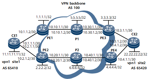
On the network shown in Figure 1, CE1 resides at Site 1 of VPN1; CE2 resides at Site 2 of VPN1; CE1 is dual-homed to PE1 and PE2; CE2 is dual-homed to PE3 and PE4.
If the traffic from CE1 to CE2 is heavy whereas the traffic from CE2 to CE1 is light, the data traffic from CE1 to CE2 can be transmitted in load balancing mode; the data traffic from CE2 to CE1 can be forwarded by PE4 with PE3 as a backup.
Device Name |
Interface |
IP Address |
CE1 |
Loopback1 |
11.11.11.11/32 |
CE1 |
GE0/1/0 |
10.1.1.1/30 |
CE1 |
GE0/1/8 |
10.2.1.1/30 |
PE1 |
Loopback1 |
1.1.1.1/32 |
PE1 |
GE0/1/0 |
10.1.1.2/30 |
PE1 |
GE0/1/8 |
10.10.1.1/30 |
PE2 |
Loopback1 |
2.2.2.2/32 |
PE2 |
GE0/1/0 |
10.2.1.2/30 |
PE2 |
GE0/1/8 |
10.20.1.1/30 |
P1 |
Loopback1 |
5.5.5.5/32 |
P1 |
GE0/1/0 |
10.10.1.2/30 |
P1 |
GE0/1/8 |
10.30.1.1/30 |
P2 |
Loopback1 |
6.6.6.6/32 |
P2 |
GE0/1/0 |
10.20.1.2/30 |
P2 |
GE0/1/8 |
10.40.1.1/30 |
PE3 |
Loopback1 |
3.3.3.3/32 |
PE3 |
GE0/1/0 |
10.30.1.2/30 |
PE3 |
GE0/1/8 |
10.3.1.1/30 |
PE4 |
Loopback1 |
4.4.4.4/32 |
PE4 |
GE0/1/0 |
10.40.1.2/30 |
PE4 |
GE0/1/8 |
10.4.1.1/30 |
CE2 |
Loopback1 |
22.22.22.22/32 |
CE2 |
GE0/1/0 |
10.3.1.2/30 |
CE2 |
GE0/1/8 |
10.4.1.2/30 |
Configuration Notes
When configuring CE dual-homing with EBGP running between the PEs and CE, ensure that the CE is dual-homed to two PEs configured with VPN instances of different RDs.
Configuration Roadmap
The configuration roadmap is as follows:
Configure a basic BGP/MPLS IP VPN.
Configure load balancing for the traffic from CE1 to CE2 in the BGP view of CE1.
Increase the Multi-Exit Discrimination (MED) value of the BGP-VPN route on PE3 to ensure that the next hop of the route selected by CE2 to the users who access CE1 is PE4.
Data Preparation
To complete the configuration, you need the following data:
MPLS LSR IDs of the PEs and P
Names of the VPN instances, RDs, and VPN targets of the PEs
AS numbers of the CEs
Procedure
- Configure an IGP on the MPLS backbone network for devices on the MPLS backbone network to communicate.
# Assign an IP address to each interface on PE1. Note that the IP address of a loopback interface has a 32-bit mask.
<HUAWEI> system-view
[~HUAWEI] sysname PE1
[*HUAWEI] commit
[~PE1] interface loopback 1
[*PE1-LoopBack1] ip address 1.1.1.1 32
[*PE1-LoopBack1] commit
[*PE1-LoopBack1] quit
[*PE1] interface gigabitethernet0/1/8
[*PE1-GigabitEthernet0/1/8] ip address 10.10.1.1 30
[*PE1-GigabitEthernet0/1/8] commit
[~PE1-GigabitEthernet0/1/8] quit
# Configure IS-IS to advertise routes of each interface.
[~PE1] isis 1
[*PE1-isis-1] network-entity 10.0000.0000.0001.00
[*PE1-isis-1] commit
[*PE1-isis-1] quit
[*PE1] interface loopback 1
[*PE1-LoopBack1] isis enable 1
[*PE1-LoopBack1] commit
[*PE1-LoopBack1] quit
[*PE1] interface gigabitethernet0/1/8
[*PE1-GigabitEthernet0/1/8] isis enable 1
[*PE1-GigabitEthernet0/1/8] commit
[~PE1-GigabitEthernet0/1/8] quit
# The configurations of other devices on the backbone network are similar to the configuration of PE1. For configuration details, see Configuration Files in this section.
After completing the configurations, run the display ip routing-table command. The command output shows that PE1 and PE3, and PE2 and PE4 have learned the routes to Loopback 1 of each other.
The following example uses the command output on PE1.
<PE1> display ip routing-table
Route Flags: R - relay, D - download to fib, T - to vpn-instance, B - black hole route
------------------------------------------------------------------------------
Routing Table: _public_
         Destinations : 11        Routes : 11
  Destination/Mask  Proto  Pre  Cost       Flags  NextHop         Interface
        1.1.1.1/32  Direct 0    0              D  127.0.0.1       InLoopBack0
        3.3.3.3/32  ISIS   15   20             D  10.10.1.2       GigabitEthernet0/1/8
        5.5.5.5/32  ISIS   15   10             D  10.10.1.2       GigabitEthernet0/1/8
      10.10.1.0/30  Direct 0    0              D  10.10.1.1       GigabitEthernet0/1/8
      10.10.1.1/32  Direct 0    0              D  127.0.0.1       GigabitEthernet0/1/8
    10.10.1.255/32  Direct 0    0              D  127.0.0.1       GigabitEthernet0/1/8
      10.30.1.0/30  ISIS   15   20             D  10.10.1.2       GigabitEthernet0/1/8
      127.0.0.0/8   Direct 0    0              D  127.0.0.1       InLoopBack0
      127.0.0.1/32  Direct 0    0              D  127.0.0.1       InLoopBack0
127.255.255.255/32  Direct 0    0              D  127.0.0.1       InLoopBack0
255.255.255.255/32  Direct 0    0              D  127.0.0.1       InLoopBack0
- Configure MPLS and MPLS LDP both globally and per interface on each node of the backbone network and set up LDP LSPs.
# Configure PE1.
[~PE1] mpls lsr-id 1.1.1.1
[*PE1] mpls
[*PE1-mpls] quit
[*PE1] mpls ldp
[*PE1-mpls-ldp] quit
[*PE1] interface gigabitethernet 0/1/8
[*PE1-GigabitEthernet0/1/8] mpls
[*PE1-GigabitEthernet0/1/8] mpls ldp
[*PE1-GigabitEthernet0/1/8] commit
[~PE1-GigabitEthernet0/1/8] quit
# The configurations of other devices on the backbone network are similar to the configuration of PE1. For configuration details, see Configuration Files in this section.
After the configurations are complete, LDP sessions can be set up between PE1 and the P and between the P and PE2. Run the display mpls ldp session command. The command output shows that the Status field is Operational. Run the display mpls ldp lsp command. The command output shows whether LDP LSPs are set up.
The following example uses the command output on PE1.
<PE1> display mpls ldp session LDP Session(s) in Public Network Codes: LAM(Label Advertisement Mode), SsnAge Unit(DDDD:HH:MM) An asterisk (*) before a session means the session is being deleted. ------------------------------------------------------------------------------ Peer-ID Status LAM SsnRole SsnAge KA-Sent/Rcv ------------------------------------------------------------------------------ 5.5.5.5:0 Operational DU Passive 0000:07:02 1688/1688 ------------------------------------------------------------------------------ TOTAL: 1 session(s) Found. <PE1> display mpls ldp lsp LDP LSP Information ------------------------------------------------------------------------------- DestAddress/Mask In/OutLabel UpstreamPeer NextHop OutInterface ------------------------------------------------------------------------------- 1.1.1.1/32 3/NULL 5.5.5.5 127.0.0.1 Loop1 *1.1.1.1/32 Liberal/16 DS/5.5.5.5 3.3.3.3/32 NULL/17 - 10.10.1.2 GE0/1/8 3.3.3.3/32 17/17 5.5.5.5 10.10.1.2 GE0/1/8 5.5.5.5/32 NULL/3 - 10.10.1.2 GE0/1/8 5.5.5.5/32 16/3 5.5.5.5 10.10.1.2 GE0/1/8 ------------------------------------------------------------------------------- TOTAL: 5 Normal LSP(s) Found. TOTAL: 1 Liberal LSP(s) Found. TOTAL: 0 Frr LSP(s) Found. An asterisk (*) before an LSP means the LSP is not established An asterisk (*) before a Label means the USCB or DSCB is stale An asterisk (*) before an UpstreamPeer means the session is stale An asterisk (*) before a DS means the session is stale An asterisk (*) before a NextHop means the LSP is FRR LSP - Configure an IPv4-address-family-supporting VPN instance on each PE and bind the interface that connects a PE to a CE to the VPN instance on that PE.
# Configure PE1. Configure vpn1 and specify its RD and VPN targets. The VPN targets configured on the local PE must match the VPN targets of the MP-BGP peer PE so that sites in the same VPN can communicate with each other.
[~PE1] ip vpn-instance vpn1
[*PE1-vpn-instance-vpn1] ipv4-family
[*PE1-vpn-instance-vpn1-af-ipv4] route-distinguisher 100:1
[*PE1-vpn-instance-vpn1-af-ipv4] vpn-target 1:1 both
[*PE1-vpn-instance-vpn1-af-ipv4] commit
[~PE1-vpn-instance-vpn1-af-ipv4] quit
[~PE1-vpn-instance-vpn1] quit
# Bind the interface that connects PE1 to a CE to the VPN instance on PE1, and assign an IP address to the interface.
[~PE1] interface gigabitethernet 0/1/0
[~PE1-GigabitEthernet0/1/0] ip binding vpn-instance vpn1
[*PE1-GigabitEthernet0/1/0] ip address 10.1.1.2 30
[*PE1-GigabitEthernet0/1/0] commit
[~PE1-GigabitEthernet0/1/0] quit
# The configurations of PE2, PE3, and PE4 are similar to the configuration of PE1. For configuration details, see Configuration Files in this section.
After completing the configurations, run the display ip vpn-instance verbose command on PEs to check the configurations of VPN instances.
The following example uses the command output on PE1.
<PE1> display ip vpn-instance verbose Total VPN-Instances configured : 1 Total IPv4 VPN-Instances configured : 1 Total IPv6 VPN-Instances configured : 0 VPN-Instance Name and ID : vpn1, 1 Interfaces : GigabitEthernet0/1/0 Address family ipv4 Create date : 2020-10-09 07:28:20+00:00 Up time : 0 days, 07 hours, 23 minutes and 53 seconds Vrf Status : UP Route Distinguisher : 100:1 Export VPN Targets : 1:1 Import VPN Targets : 1:1 Label policy : label per instance Per-Instance Label : 48311 The diffserv-mode Information is : uniform The ttl-mode Information is : pipe - Configure EBGP on the PEs and CEs and import VPN routes.
# Assign an IP address to each interface on CEs, as shown in Figure 1. The detailed configuration is not mentioned here. For configuration details, see Configuration Files in this section.
# On CE1, specify PE1 and PE2 as EBGP peers.
[~CE1] interface loopback 1
[*CE1-LoopBack1] ip address 11.11.11.11 32
[*CE1-LoopBack1] quit
[*CE1] bgp 65410
[*CE1-bgp] peer 10.1.1.2 as-number 100
[*CE1-bgp] peer 10.2.1.2 as-number 100
[*CE1-bgp] network 11.11.11.11 32
[*CE1-bgp] commit
[~CE1-bgp] quit
# On PE1, specify CE1 as an EBGP peer.
[~PE1] bgp 100
[*PE1-bgp] ipv4-family vpn-instance vpn1
[*PE1-bgp-vpn1] peer 10.1.1.1 as-number 65410
[*PE1-bgp-vpn1] commit
[~PE1-bgp-vpn1] quit
# On PE2, specify CE1 as an EBGP peer.
[~PE2] bgp 100
[*PE2-bgp] ipv4-family vpn-instance vpn1
[*PE2-bgp-vpn1] peer 10.2.1.1 as-number 65410
[*PE2-bgp-vpn1] commit
[~PE2-bgp-vpn1] quit
# On CE2, specify PE3 and PE4 as EBGP peers.
[~CE2] interface loopback 1
[*CE2-LoopBack1] ip address 22.22.22.22 32
[*CE2-LoopBack1] quit
[*CE2] bgp 65420
[*CE2-bgp] peer 10.3.1.1 as-number 100
[*CE2-bgp] peer 10.4.1.1 as-number 100
[*CE2-bgp] network 22.22.22.22 32
[*CE2-bgp] commit
[~CE2-bgp] quit
# On PE3, specify CE2 as an EBGP peer.
[~PE3] bgp 100
[*PE3-bgp] ipv4-family vpn-instance vpn1
[*PE3-bgp-vpn1] peer 10.3.1.2 as-number 65420
[*PE3-bgp-vpn1] commit
[~PE3-bgp-vpn1] quit
# On PE4, specify CE2 as an EBGP peer.
[~PE4] bgp 100
[*PE4-bgp] ipv4-family vpn-instance vpn1
[*PE4-bgp-vpn1] peer 10.4.1.2 as-number 65420
[*PE4-bgp-vpn1] commit
[~PE4-bgp-vpn1] quit
After completing the configurations, run the display bgp vpnv4 vpn-instance peer command on PEs. The command output shows that BGP peer relationships have been established between PEs and CEs.
The following example uses the peer relationship between PE1 and CE1.
<PE1> display bgp vpnv4 vpn-instance vpn1 peer
 BGP local router ID : 1.1.1.1
 Local AS number : 100
 Total number of peers : 1                 Peers in established state : 1
  Peer            V    AS  MsgRcvd  MsgSent  OutQ  Up/Down       State PrefRcv
  10.1.1.1        4 65410      408      435     0 06:16:09 Established       5
Each PE can successfully ping its connected CE. The following example uses the command output on PE1.
<PE1> ping -vpn-instance vpn1 11.11.11.11 PING 11.11.11.11: 56 data bytes, press CTRL_C to break Reply from 11.11.11.11: bytes=56 Sequence=1 ttl=254 time=80 ms Reply from 11.11.11.11: bytes=56 Sequence=2 ttl=254 time=20 ms Reply from 11.11.11.11: bytes=56 Sequence=3 ttl=254 time=30 ms Reply from 11.11.11.11: bytes=56 Sequence=4 ttl=254 time=50 ms Reply from 11.11.11.11: bytes=56 Sequence=5 ttl=254 time=30 ms --- 11.11.11.11 ping statistics --- 5 packet(s) transmitted 5 packet(s) received 0.00% packet loss round-trip min/avg/max = 20/42/80 ms - Set up an MP-IBGP peer relationship between PEs.
# On PE1, specify PE3 as the IBGP peer and establish an IBGP peer relationship between PE1 and PE3 through loopback interfaces.
[~PE1] bgp 100
[~PE1-bgp] peer 3.3.3.3 as-number 100
[*PE1-bgp] peer 3.3.3.3 connect-interface loopback 1
[*PE1-bgp] ipv4-family vpnv4
[*PE1-bgp-af-vpnv4] peer 3.3.3.3 enable
[*PE1-bgp-af-vpnv4] commit
[~PE1-bgp-af-vpnv4] quit
# On PE3, specify PE1 as the IBGP peer and establish an IBGP peer relationship between PE3 and PE1 through loopback interfaces.
[~PE3] bgp 100
[~PE3-bgp] peer 1.1.1.1 as-number 100
[*PE3-bgp] peer 1.1.1.1 connect-interface loopback 1
[~PE3-bgp] ipv4-family vpnv4
[~PE3-bgp-af-vpnv4] peer 1.1.1.1 enable
[*PE3-bgp-af-vpnv4] commit
[~PE3-bgp-af-vpnv4] quit
# On PE2, specify PE4 as the IBGP peer and establish an IBGP peer relationship between PE2 and PE4 through loopback interfaces.
[~PE2] bgp 100
[~PE2-bgp] peer 4.4.4.4 as-number 100
[*PE2-bgp] peer 4.4.4.4 connect-interface loopback 1
[*PE2-bgp] ipv4-family vpnv4
[*PE2-bgp-af-vpnv4] peer 4.4.4.4 enable
[*PE2-bgp-af-vpnv4] commit
[~PE2-bgp-af-vpnv4] quit
# On PE4, specify PE2 as the IBGP peer and establish an IBGP peer relationship between PE4 and PE2 through loopback interfaces.
[~PE4] bgp 100
[~PE4-bgp] peer 2.2.2.2 as-number 100
[*PE4-bgp] peer 2.2.2.2 connect-interface loopback 1
[*PE4-bgp] ipv4-family vpnv4
[*PE4-bgp-af-vpnv4] peer 2.2.2.2 enable
[*PE4-bgp-af-vpnv4] commit
[~PE4-bgp-af-vpnv4] quit
After completing the configurations, run the display bgp peer or display bgp vpnv4 all peer command on PEs. The command output shows that BGP peer relationships have been established between PEs.
<PE1> display bgp peer
 BGP local router ID : 1.1.1.1
 Local AS number : 100
 Total number of peers : 1          Peers in established state : 1
  Peer                V    AS  MsgRcvd  MsgSent  OutQ  Up/Down       State PrefRcv
  3.3.3.3             4   100        2        6     0 00:00:12 Established      0
<PE1> display bgp vpnv4 all peer
BGP local router ID : 1.1.1.1
 Local AS number : 100
 Total number of peers : 2                 Peers in established state : 2
  Peer            V    AS  MsgRcvd  MsgSent  OutQ  Up/Down       State PrefRcv
  3.3.3.3         4   100       12       18     0 00:09:38 Established       0
  Peer of vpn instance:
  VPN-Instance vpn1, router ID 1.1.1.1:
  10.1.1.1        4 65410       25       25     0 00:17:57 Established       1
- On CE1, enable load balancing for the traffic from CE1 to CE2.
[~CE1] bgp 65410
[~CE1-bgp] ipv4-family unicast
[~CE1-bgp-af-ipv4] maximum load-balancing 2
[*CE1-bgp-af-ipv4] commit
- Configure a routing policy. Increase the MED value of the BGP route advertised by PE3 to CE2 and ensure that the traffic from CE2 to CE1 passes through PE4. PE3 functions as a backup.
[~PE3] route-policy policy1 permit node 10
[*PE3-route-policy] apply cost 120
[*PE3-route-policy] commit
[*PE3-route-policy] quit
[*PE3] bgp 100
[*PE3-bgp] ipv4-family vpn-instance vpn1
[*PE3-bgp-vpn1] peer 10.3.1.2 route-policy policy1 export
[*PE3-bgp-vpn1] commit
Run the display bgp routing-table command to check information about the BGP routing table on CE2. The command output shows that for the route to 11.11.11.11/32, the MED value advertised by PE3 is 120. This value is greater than the MED value advertised by PE4. Therefore, the MED value advertised by PE4 is chosen.
<CE2> display bgp routing-table
 BGP Local router ID is 11.11.11.11
 Status codes: * - valid, > - best, d - damped, x - best external, a - add path,
               h - history,  i - internal, s - suppressed, S - Stale
               Origin : i - IGP, e - EGP, ? - incomplete
 RPKI validation codes: V - valid, I - invalid, N - not-found
 Total Number of Routes: 2
      Network            NextHop        MED        LocPrf    PrefVal Path/Ogn
 *>   11.11.11.11/32         10.4.1.1                              0      100 65410?
 *                           10.3.1.1        120                   0      100 65410?
 *>   22.22.22.22/32         0.0.0.0         0                     0      ?
- Verify the configuration.
Run the display ip routing-table command on CE1. The command output shows the routes to the users connected to CE2 and that traffic is transmitted in load balancing mode.
<CE1> display ip routing-table
Route Flags: R - relay, D - download to fib, T - to vpn-instance, B - black hole route
------------------------------------------------------------------------------
Routing Table: _public_
         Destinations : 12       Routes : 13

Destination/Mask    Proto  Pre  Cost        Flags NextHop         Interface

       10.1.1.0/30  Direct 0    0             D  10.1.1.1        Gigabitethernet0/1/0
       10.1.1.1/32  Direct 0    0             D  127.0.0.1       Gigabitethernet0/1/0
     10.1.1.255/32  Direct 0    0             D  127.0.0.1       Gigabitethernet0/1/0
       10.2.1.0/30  Direct 0    0             D  10.2.1.1        Gigabitethernet0/1/8
       10.2.1.1/32  Direct 0    0             D  127.0.0.1       Gigabitethernet0/1/8
     10.2.1.255/32  Direct 0    0             D  127.0.0.1       Gigabitethernet0/1/8
    11.11.11.11/32  Direct 0    0             D  127.0.0.1       LoopBack1
    22.22.22.22/32  EBGP   255  0             D  10.1.1.2        Gigabitethernet0/1/0
                    EBGP   255  0             D  10.2.1.2        Gigabitethernet0/1/8
      127.0.0.0/8   Direct 0    0             D  127.0.0.1       InLoopBack0
      127.0.0.1/32  Direct 0    0             D  127.0.0.1       InLoopBack0
127.255.255.255/32  Direct 0    0             D  127.0.0.1       InLoopBack0
255.255.255.255/32  Direct 0    0             D  127.0.0.1       InLoopBack0
Run the display ip routing-table command on CE2. The command output shows the routes to the users connected to CE1. The command output also shows that the next hop of the routes is 10.4.1.1, the IP address of the interface that connects PE4 to CE2.
<CE2> display ip routing-table
Route Flags: R - relay, D - download to fib, T - to vpn-instance, B - black hole route
------------------------------------------------------------------------------
Routing Table: _public_
         Destinations : 12       Routes : 12

Destination/Mask    Proto  Pre  Cost        Flags NextHop         Interface

    11.11.11.11/32  EBGP   255  0             D  10.4.1.1        Gigabitethernet0/1/8
    22.22.22.22/32  Direct 0    0             D  127.0.0.1         LoopBack1
       10.3.1.0/30  Direct 0    0             D  10.3.1.2        GigabitEthernet0/1/0
       10.3.1.2/32  Direct 0    0             D  127.0.0.1       GigabitEthernet0/1/0
     10.3.1.255/32  Direct 0    0             D  127.0.0.1       GigabitEthernet0/1/0
       10.4.1.0/30  Direct 0    0             D  10.4.1.2        Gigabitethernet0/1/8
       10.4.1.2/32  Direct 0    0             D  127.0.0.1       Gigabitethernet0/1/8
     10.4.1.255/32  Direct 0    0             D  127.0.0.1       Gigabitethernet0/1/8
      127.0.0.0/8   Direct 0    0             D  127.0.0.1       InLoopBack0
      127.0.0.1/32  Direct 0    0             D  127.0.0.1       InLoopBack0
127.255.255.255/32  Direct 0    0             D  127.0.0.1       InLoopBack0
255.255.255.255/32  Direct 0    0             D  127.0.0.1       InLoopBack0
Configuration Files
CE1 configuration file
#
 sysname CE1
#
interface Gigabitethernet0/1/0
 undo shutdown
ip address 10.1.1.1 255.255.255.252
#
interface Gigabitethernet0/1/8
 undo shutdown
ip address 10.2.1.1 255.255.255.252
#
interface Loopback1
 undo shutdown
 ip address 11.11.11.11 255.255.255.255
#
bgp 65410
 peer 10.1.1.2 as-number 100
 peer 10.2.1.2 as-number 100
 #
 ipv4-family unicast
  undo synchronization
  network 11.11.11.11 255.255.255.255
  maximum load-balancing 2
  peer 10.1.1.2 enable
  peer 10.2.1.2 enable
#
return
PE1 configuration file
#
 sysname PE1
#
ip vpn-instance vpn1
 ipv4-family
  route-distinguisher 100:1
  apply-label per-instance
  vpn-target 1:1 export-extcommunity
  vpn-target 1:1 import-extcommunity
#
 mpls lsr-id 1.1.1.1
 mpls
#
mpls ldp
#
isis 1
 network-entity 10.0000.0000.0001.00
#
interface Gigabitethernet0/1/0
 undo shutdown
ip binding vpn-instance vpn1
 ip address 10.1.1.2 255.255.255.252
#
interface GigabitEthernet0/1/8
 undo shutdown
 ip address 10.10.1.1 255.255.255.252
 isis enable 1
 mpls
 mpls ldp
#
interface LoopBack1
 ip address 1.1.1.1 255.255.255.255
 isis enable 1
#
bgp 100
 peer 3.3.3.3 as-number 100
 peer 3.3.3.3 connect-interface LoopBack1
 #
 ipv4-family unicast
  undo synchronization
  peer 3.3.3.3 enable
 #
 ipv4-family vpnv4
  policy vpn-target
  peer 3.3.3.3 enable
 #
 ipv4-family vpn-instance vpn1
  peer 10.1.1.1 as-number 65410
#
Return
PE2 configuration file
#
 sysname PE2
#
ip vpn-instance vpn1
 ipv4-family
  route-distinguisher 100:2
  apply-label per-instance
  vpn-target 1:1 export-extcommunity
  vpn-target 1:1 import-extcommunity
#
mpls lsr-id 2.2.2.2
#
mpls
#
mpls ldp
#
isis 1
 network-entity 10.0000.0000.0002.00
#
interface Gigabitethernet0/1/0
 undo shutdown
 ip binding vpn-instance vpn1
 ip address 10.2.1.2 255.255.255.252
#
interface GigabitEthernet0/1/8
 undo shutdown
 ip address 10.20.1.1 255.255.255.252
 isis enable 1
 mpls
 mpls ldp
#
interface LoopBack1
 ip address 2.2.2.2 255.255.255.255
 isis enable 1
#
bgp 100
 peer 4.4.4.4 as-number 100
 peer 4.4.4.4 connect-interface LoopBack1
 #
 ipv4-family unicast
  undo synchronization
  peer 4.4.4.4 enable
 #
 ipv4-family vpnv4
  policy vpn-target
  peer 4.4.4.4 enable
 #
 ipv4-family vpn-instance vpn1
  peer 10.2.1.1 as-number 65410
#
Return
P1 configuration file
#
 sysname P1
#
mpls lsr-id 5.5.5.5
#
mpls
#
mpls ldp
#
isis 1
 network-entity 10.0000.0000.0005.00
#
interface GigabitEthernet0/1/0
 undo shutdown
 ip address 10.10.1.2 255.255.255.252
 isis enable 1
 mpls
 mpls ldp
#
interface GigabitEthernet0/1/8
 undo shutdown
 ip address 10.30.1.1 255.255.255.252
 isis enable 1
 mpls
 mpls ldp
#
interface LoopBack1
 ip address 5.5.5.5 255.255.255.255
 isis enable 1
#
Return
P2 configuration file
#
 sysname P2
#
mpls lsr-id 6.6.6.6
#
mpls
#
mpls ldp
#
isis 1
 network-entity 10.0000.0000.0006.00
#
interface GigabitEthernet0/1/0
 undo shutdown
 ip address 10.20.1.2 255.255.255.252
 mpls
 mpls ldp
 isis enable 1
#
interface GigabitEthernet0/1/8
 undo shutdown
 ip address 10.40.1.1 255.255.255.252
 mpls
 mpls ldp
 isis enable 1
#
interface LoopBack1
 ip address 6.6.6.6 255.255.255.255
 isis enable 1
#
Return
PE3 configuration file
sysname PE3
#
ip vpn-instance vpn1
 ipv4-family
  route-distinguisher 100:3
  apply-label per-instance
  vpn-target 1:1 export-extcommunity
  vpn-target 1:1 import-extcommunity
#
mpls lsr-id 3.3.3.3
#
mpls
#
mpls ldp
#
isis 1
 network-entity 10.0000.0000.0003.00
#
interface GigabitEthernet0/1/0
 undo shutdown
 ip address 10.30.1.2 255.255.255.252
 mpls
 mpls ldp
 isis enable 1
#
interface Gigabitethernet0/1/8
 undo shutdown
 ip binding vpn-instance vpn1
 ip address 10.3.1.1 255.255.255.252
#
interface LoopBack1
 ip address 3.3.3.3 255.255.255.255
 isis enable 1
#
bgp 100
 peer 1.1.1.1 as-number 100
 peer 1.1.1.1 connect-interface LoopBack1
 #
 ipv4-family unicast
  undo synchronization
  peer 1.1.1.1 enable
 #
 ipv4-family vpnv4
  policy vpn-target
  peer 1.1.1.1 enable
 #
 ipv4-family vpn-instance vpn1
  peer 10.3.1.2 as-number 65420
  peer 10.3.1.2 route-policy policy1 export
#
route-policy policy1 permit node 10
 apply cost 120
#
Return
PE4 configuration file
#
sysname PE4
#
ip vpn-instance vpn1
 ipv4-family
  route-distinguisher 100:4
  apply-label per-instance
  vpn-target 1:1 export-extcommunity
  vpn-target 1:1 import-extcommunity
#
mpls lsr-id 4.4.4.4
#
mpls
#
mpls ldp
#
isis 1
 network-entity 10.0000.0000.0004.00
#
interface GigabitEthernet0/1/0
 undo shutdown
 ip address 10.40.1.2 255.255.255.252
 mpls
 mpls ldp
 isis enable 1
#
interface Gigabitethernet0/1/8
 undo shutdown
 ip binding vpn-instance vpn1
 ip address 10.4.1.1 255.255.255.252
#
interface LoopBack1
 ip address 4.4.4.4 255.255.255.255
 isis enable 1
#
bgp 100
 peer 2.2.2.2 as-number 100
 peer 2.2.2.2 connect-interface LoopBack1
 #
 ipv4-family unicast
  undo synchronization
  peer 2.2.2.2 enable
 #
 ipv4-family vpnv4
  policy vpn-target
  peer 2.2.2.2 enable
 #
 ipv4-family vpn-instance vpn1
  peer 10.4.1.2 as-number 65420
#
Return
CE2 configuration file
#
 sysname CE2
#
interface Gigabitethernet0/1/0
 undo shutdown
 ip address 10.3.1.2 255.255.255.252
#
interface Gigabitethernet0/1/8
 undo shutdown
 ip address 10.4.1.2 255.255.255.252
#
interface Loopback1
 undo shutdown
 ip address 22.22.22.22 255.255.255.255
#
bgp 65420
 peer 10.3.1.1 as-number 100
 peer 10.4.1.1 as-number 100
 #
 ipv4-family unicast
  undo synchronization
  network 22.22.22.22 255.255.255.255
  peer 10.3.1.1 enable
  peer 10.4.1.1 enable
#
Return