Example for Configuring Two RRs for the Optimization of the VPN Backbone Layer
If a great number of MP-IBGP connections exist between PEs, you can configure RRs to reduce the number of MP-IBGP connections and the workload of PEs, optimizing the VPN backbone layer.
Networking Requirements
When deploying a VPN, you can configure two RRs on the VPN to improve reliability. To achieve this, you need to configure two Ps in the same AS on the backbone network as RRs and ensure that the two RRs back up each other and reflect VPNv4 and public network routes.

Interfaces 1 through 3 in this example represent GE 0/1/0, GE 0/1/8, and GE 0/1/16, respectively.
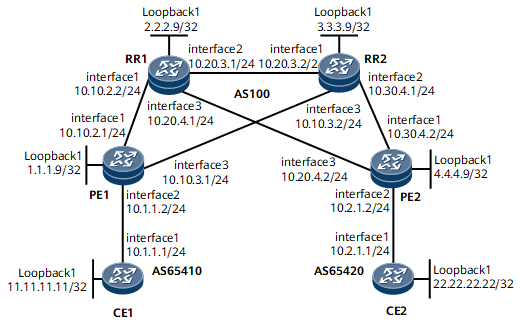
On the network shown in Figure 1, PE1, PE2, RR1, and RR2 are in AS100 of the backbone network. CE1 and CE2 belong to vpna. It is required that RR1 and RR2 be configured as RRs.
Configuration Notes
When configuring two RRs for the optimization of the VPN backbone layer, ensure that:
The RRs do not filter the received VPNv4 routes based on VPN targets.
The RRs that back up each other are configured with the same cluster ID.
Configuration Roadmap
The configuration roadmap is as follows:
Configure an IGP, enable MPLS and MPLS LDP, and set up LDP LSPs on the MPLS backbone network.
Set up MP-IBGP connections between the PEs and RRs. There is no need to set up an MP-IBGP connection between PEs.
Set up an EBGP connection between each PE and CE.
Configure RR1 and RR2 to back up each other and configure them with the same cluster ID.
Configure RR1 and RR2 to receive all VPNv4 routes without filtering them based on VPN targets, because RR1 and RR2 must save all VPNv4 routes and advertise them to PEs.
On a VPN with two RRs, there must be at least two paths not sharing the same network segment or node between each RR and PE. Otherwise, configuring two RRs is unnecessary.
Data Preparation
To complete the configuration, you need the following data:
MPLS LSR IDs of the PEs and RRs
Names, RDs, and VPN targets of the VPN instances on PE1 and PE2
AS numbers of the PEs and CEs
BGP peer group name
Procedure
- Configure an IGP on the MPLS backbone network to implement interworking of devices along the LSP.
This example uses OSPF as the IGP. For configuration details, see Configuration Files in this section.
The loopback interface IP addresses used as LSR IDs must be advertised.
After completing the configurations, the devices along the LSP can learn the IP address of each other's loopback interface.
The following example uses the command output on PE1.
<PE1> display ip routing-table
Route Flags: R - relay, D - download to fib, T - to vpn-instance, B - black hole route
------------------------------------------------------------------------------
Routing Table: _public_
         Destinations : 17       Routes : 19
  Destination/Mask  Proto  Pre  Cost         Flags  NextHop         Interface
        1.1.1.9/32  Direct 0    0                D  127.0.0.1       InLoopBack0
        2.2.2.9/32  OSPF   10   2                D  10.10.2.2       GigabitEthernet0/1/0
        3.3.3.9/32  OSPF   10   2                D  10.10.3.2       GigabitEthernet0/1/16
        4.4.4.9/32  OSPF   10   3                D  10.10.3.2       GigabitEthernet0/1/16
                    OSPF   10   3                D  10.10.2.2       GigabitEthernet0/1/0
      10.10.2.0/24  Direct 0    0                D  10.10.2.1       GigabitEthernet0/1/0
      10.10.2.1/32  Direct 0    0                D  127.0.0.1       GigabitEthernet0/1/0
    10.10.2.255/32  Direct 0    0                D  127.0.0.1       GigabitEthernet0/1/0
      10.10.3.0/24  Direct 0    0                D  10.10.3.1       GigabitEthernet0/1/16
      10.10.3.1/32  Direct 0    0                D  127.0.0.1       GigabitEthernet0/1/16
    10.10.3.255/32  Direct 0    0                D  127.0.0.1       GigabitEthernet0/1/16
      10.20.3.0/24  OSPF   10   2                D  10.10.3.2       GigabitEthernet0/1/16
                    OSPF   10   2                D  10.10.2.2       GigabitEthernet0/1/0
      10.20.4.0/24  OSPF   10   2                D  10.10.2.2       GigabitEthernet0/1/0
      10.30.4.0/24  OSPF   10   2                D  10.10.3.2       GigabitEthernet0/1/16
      127.0.0.0/8   Direct 0    0                D  127.0.0.1       InLoopBack0
      127.0.0.1/32  Direct 0    0                D  127.0.0.1       InLoopBack0
127.255.255.255/32  Direct 0    0                D  127.0.0.1       InLoopBack0
255.255.255.255/32  Direct 0    0                D  127.0.0.1       InLoopBack0
- Set up LSPs on the MPLS backbone network.
Enable MPLS and MPLS LDP on the devices and interfaces along the LSP. For configuration details, see Configuration Files in this section.
After completing the configurations, run the display mpls ldp session command on the PEs and RRs. The command output shows that the Status field is Operational.
The following example uses the command output on PE1.
<PE1> display mpls ldp session LDP Session(s) in Public Network Codes: LAM(Label Advertisement Mode), SsnAge Unit(DDD:HH:MM) An asterisk (*) before a session means the session is being deleted. ---------------------------------------------------------------------- Peer-ID Status LAM SsnRole SsnAge KA-Sent/Rcv ---------------------------------------------------------------------- 2.2.2.9:0 Operational DU Passive 000:00:01 8/8 3.3.3.9:0 Operational DU Passive 000:00:00 4/4 ---------------------------------------------------------------------- TOTAL: 2 session(s) Found. LAM : Label Advertisement Mode SsnAge Unit : DDD:HH:MM <RR1> display mpls ldp session LDP Session(s) in Public Network Codes: LAM(Label Advertisement Mode), SsnAge Unit(DDD:HH:MM) An asterisk (*) before a session means the session is being deleted. ---------------------------------------------------------------------- Peer-ID Status LAM SsnRole SsnAge KA-Sent/Rcv ---------------------------------------------------------------------- 1.1.1.9:0 Operational DU Active 000:00:02 11/11 3.3.3.9:0 Operational DU Passive 000:00:01 8/8 4.4.4.9:0 Operational DU Passive 000:00:00 4/4 ---------------------------------------------------------------------- TOTAL: 3 session(s) Found. LAM : Label Advertisement Mode SsnAge Unit : DDD:HH:MM - Set up an MP-IBGP peer relationship between each PE and RR.
# Configure PE1.
<PE1> system-view
[~PE1] bgp 100
[*PE1-bgp] peer 2.2.2.9 as-number 100
[*PE1-bgp] peer 2.2.2.9 connect-interface loopback 1
[*PE1-bgp] peer 3.3.3.9 as-number 100
[*PE1-bgp] peer 3.3.3.9 connect-interface loopback 1
[*PE1-bgp] ipv4-family vpnv4
[*PE1-bgp-af-vpnv4] peer 2.2.2.9 enable
[*PE1-bgp-af-vpnv4] peer 3.3.3.9 enable
[*PE1-bgp-af-vpnv4] commit
[~PE1-bgp-af-vpnv4] quit
# Configure RR1.
<RR1> system-view
[~RR1] bgp 100
[*RR1-bgp] peer 1.1.1.9 as-number 100
[*RR1-bgp] peer 1.1.1.9 connect-interface loopback 1
[*RR1-bgp] peer 3.3.3.9 as-number 100
[*RR1-bgp] peer 3.3.3.9 connect-interface loopback 1
[*RR1-bgp] peer 4.4.4.9 as-number 100
[*RR1-bgp] peer 4.4.4.9 connect-interface loopback 1
[*RR1-bgp] ipv4-family vpnv4
[*RR1-bgp-af-vpnv4] peer 1.1.1.9 enable
[*RR1-bgp-af-vpnv4] peer 3.3.3.9 enable
[*RR1-bgp-af-vpnv4] peer 4.4.4.9 enable
[*RR1-bgp-af-vpnv4] commit
[~RR1-bgp-af-vpnv4] quit
[~RR1-bgp] quit
# Configure RR2.
<RR2> system-view
[~RR2] bgp 100
[*RR2-bgp] peer 1.1.1.9 as-number 100
[*RR2-bgp] peer 1.1.1.9 connect-interface loopback 1
[*RR2-bgp] peer 2.2.2.9 as-number 100
[*RR2-bgp] peer 2.2.2.9 connect-interface loopback 1
[*RR2-bgp] peer 4.4.4.9 as-number 100
[*RR2-bgp] peer 4.4.4.9 connect-interface loopback 1
[*RR2-bgp] ipv4-family vpnv4
[*RR2-bgp-af-vpnv4] peer 1.1.1.9 enable
[*RR2-bgp-af-vpnv4] peer 2.2.2.9 enable
[*RR2-bgp-af-vpnv4] peer 4.4.4.9 enable
[*RR2-bgp-af-vpnv4] commit
[~RR2-bgp-af-vpnv4] quit
[~RR2-bgp] quit
The configuration of PE2 is similar to the configuration of PE1. For configuration details, see Configuration Files in this section.
After completing the configurations, run the display bgp vpnv4 all peer command on PEs. The command output shows that the IBGP peer relationship is established between each PE and RR, and the EBGP peer relationship is established between each PE and CE.
The following example uses the command output on PE1.
<PE1> display bgp vpnv4 all peer
 BGP local router ID : 1.1.1.9
 Local AS number : 100
 Total number of peers : 3                 Peers in established state : 3
  Peer          V    AS  MsgRcvd  MsgSent  OutQ  Up/Down       State PrefRcv
  2.2.2.9      4    100  2        4         0   00:00:31    Established   0
  3.3.3.9      4    100  3        5         0   00:01:23    Established   0
- Set up EBGP peer relationships between PEs and CEs to import VPN routes.
For details, see Example for Configuring BGP/MPLS IP VPN.
- Configure a VPN instance enabled with the IPv4 address family on each PE.
For details, see Example for Configuring BGP/MPLS IP VPN.
- Configure route reflection on RR1 and RR2.
# Configure RR1.
[~RR1] bgp 100
[~RR1-bgp] ipv4-family vpnv4
[*RR1-bgp-af-vpnv4] reflector cluster-id 100
[*RR1-bgp-af-vpnv4] peer 1.1.1.9 reflect-client
[*RR1-bgp-af-vpnv4] peer 3.3.3.9 reflect-client
[*RR1-bgp-af-vpnv4] peer 4.4.4.9 reflect-client
[*RR1-bgp-af-vpnv4] undo policy vpn-target
[*RR1-bgp-af-vpnv4] commit
[~RR1-bgp-af-vpnv4] quit
# Configure RR2.
[*RR2] bgp 100
[*RR2-bgp] ipv4-family vpnv4
[*RR2-bgp-af-vpnv4] reflector cluster-id 100
[*RR2-bgp-af-vpnv4] peer 1.1.1.9 reflect-client
[*RR2-bgp-af-vpnv4] peer 2.2.2.9 reflect-client
[*RR2-bgp-af-vpnv4] peer 4.4.4.9 reflect-client
[*RR2-bgp-af-vpnv4] undo policy vpn-target
[*RR2-bgp-af-vpnv4] commit
[~RR2-bgp-af-vpnv4] quit
- Verify the configuration.
Check the VPN routing table on the PEs. The command output shows routes to the loopback interfaces of the remote CEs.
The following example uses the command output on PE1.
<PE1> display ip routing-table vpn-instance vpna
Route Flags: R - relay, D - download to fib, T - to vpn-instance, B - black hole route
------------------------------------------------------------------------------
Routing Table: vpna
         Destinations : 3        Routes : 3
  Destination/Mask  Proto  Pre  Cost         Flags  NextHop         Interface
    11.11.11.11/32  EBGP   255  0               RD  10.1.1.1        GigabitEthernet0/1/8
   22.22.22.22/32  IBGP   255  0               RD  4.4.4.9         GigabitEthernet0/1/16
255.255.255.255/32  Direct 0    0                D  127.0.0.1       InLoopBack0
CE1 and CE2 can successfully ping each other. This indicates that the configuration succeeds.
After the shutdown command is run in the view of GE 0/1/16 on PE1 or GE 0/1/16 on PE2, CE1 and CE2 can still successfully ping each other. This indicates that the two RRs are successfully configured.
Configuration Files
PE1 configuration file
#
sysname PE1
#
ip vpn-instance vpna
 ipv4-family
  route-distinguisher 100:1
  apply-label per-instance
  vpn-target 1:1 export-extcommunity
  vpn-target 1:1 import-extcommunity
#
mpls lsr-id 1.1.1.9
#
mpls
#
mpls ldp
#
interface GigabitEthernet0/1/0
 undo shutdown
 ip address 10.10.2.1 255.255.255.0
 mpls
 mpls ldp
#
interface GigabitEthernet0/1/8
 undo shutdown
 ip binding vpn-instance vpna
 ip address 10.1.1.2 255.255.255.0
#
interface GigabitEthernet0/1/16
 undo shutdown
 ip address 10.10.3.1 255.255.255.0
 mpls
 mpls ldp
#
interface LoopBack1
 ip address 1.1.1.9 255.255.255.255
#
bgp 100
 peer 2.2.2.9 as-number 100
 peer 2.2.2.9 connect-interface LoopBack1
 peer 3.3.3.9 as-number 100
 peer 3.3.3.9 connect-interface LoopBack1
 #
 ipv4-family unicast

  undo synchronization
  peer 2.2.2.9 enable
  peer 3.3.3.9 enable
 #
 ipv4-family vpnv4
  policy vpn-target
  peer 2.2.2.9 enable
  peer 3.3.3.9 enable
 #
 ipv4-family vpn-instance vpna
  peer 10.1.1.1 as-number 65410
#
ospf 1
 area 0.0.0.0
  network 1.1.1.9 0.0.0.0
  network 10.10.2.0 0.0.0.255
  network 10.10.3.0 0.0.0.255
#
return
RR1 configuration file
#
sysname RR1
#
mpls lsr-id 2.2.2.9
#
mpls
#
mpls ldp
#
interface GigabitEthernet0/1/0
 undo shutdown
 ip address 10.10.2.2 255.255.255.0
 mpls
 mpls ldp
#
interface GigabitEthernet0/1/8
 undo shutdown
 ip address 10.20.3.1 255.255.255.0
 mpls
 mpls ldp
#
interface GigabitEthernet0/1/16
 undo shutdown
 ip address 10.20.4.1 255.255.255.0
 mpls
 mpls ldp
#
interface LoopBack1
 ip address 2.2.2.9 255.255.255.255
#
bgp 100
 peer 1.1.1.9 as-number 100
 peer 1.1.1.9 connect-interface loopback 1
 peer 3.3.3.9 as-number 100
 peer 3.3.3.9 connect-interface loopback 1
 peer 4.4.4.9 as-number 100
 peer 4.4.4.9 connect-interface loopback 1
 #
 ipv4-family unicast
  undo synchronization
  peer 4.4.4.9 enable
  peer 1.1.1.9 enable
  peer 3.3.3.9 enable
 #
 ipv4-family vpnv4
  reflector cluster-id 100
  undo policy vpn-target
  peer 1.1.1.9 enable
  peer 1.1.1.9 reflect-client
  peer 3.3.3.9 enable
  peer 3.3.3.9 reflect-client
  peer 4.4.4.9 enable
  peer 4.4.4.9 reflect-client
#
ospf 1
 area 0.0.0.0
  network 10.10.2.0 0.0.0.255
  network 10.20.3.0 0.0.0.255
  network 10.20.4.0 0.0.0.255
  network 2.2.2.9 0.0.0.0
#
return
RR2 configuration file
#
sysname RR2
#
mpls lsr-id 3.3.3.9
#
mpls
#
mpls ldp
#
interface GigabitEthernet0/1/0
 undo shutdown
 ip address 10.20.3.2 255.255.255.0
 mpls
 mpls ldp
#
interface GigabitEthernet0/1/8
 undo shutdown
 ip address 10.30.4.1 255.255.255.0
 mpls
 mpls ldp
#
interface GigabitEthernet0/1/16
 undo shutdown
 ip address 10.10.3.2 255.255.255.0
 mpls
 mpls ldp
#
interface LoopBack1
 ip address 3.3.3.9 255.255.255.255
#
bgp 100
 peer 1.1.1.9 as-number 100
 peer 1.1.1.9 connect-interface LoopBack1
 peer 2.2.2.9 as-number 100
 peer 2.2.2.9 connect-interface LoopBack1
 peer 4.4.4.9 as-number 100
 peer 4.4.4.9 connect-interface LoopBack1
 #
 ipv4-family unicast
  undo synchronization
  peer 1.1.1.9 enable
  peer 2.2.2.9 enable
  peer 4.4.4.9 enable
 #
 ipv4-family vpnv4
  reflector cluster-id 100
  undo policy vpn-target
  peer 1.1.1.9 enable
  peer 1.1.1.9 reflect-client
  peer 2.2.2.9 enable
  peer 2.2.2.9 reflect-client
  peer 4.4.4.9 enable
  peer 4.4.4.9 reflect-client
#
ospf 1
 area 0.0.0.0
  network 10.20.3.0 0.0.0.255
  network 10.30.4.0 0.0.0.255
  network 10.10.3.0 0.0.0.255
  network 3.3.3.9 0.0.0.0
#
return
PE2 configuration file
#
sysname PE2
#
ip vpn-instance vpna
 ipv4-family
  route-distinguisher 100:1
  apply-label per-instance
  vpn-target 1:1 export-extcommunity
  vpn-target 1:1 import-extcommunity
#
mpls lsr-id 4.4.4.9
#
mpls
#
mpls ldp
#
interface GigabitEthernet0/1/0
 undo shutdown
 ip address 10.30.4.2 255.255.255.0
 mpls
 mpls ldp
#
interface GigabitEthernet0/1/8
 undo shutdown
 ip binding vpn-instance vpna
 ip address 10.2.1.2 255.255.255.0
#
interface GigabitEthernet0/1/16
 undo shutdown
 ip address 10.20.4.2 255.255.255.0
 mpls
 mpls ldp
#
interface LoopBack1
 ip address 4.4.4.9 255.255.255.255
#
bgp 100
 peer 2.2.2.9 as-number 100
 peer 2.2.2.9 connect-interface LoopBack1
 peer 3.3.3.9 as-number 100
 peer 3.3.3.9 connect-interface LoopBack1
 #
 ipv4-family unicast
  undo synchronization
  peer 2.2.2.9 enable
  peer 3.3.3.9 enable
 #
 ipv4-family vpnv4
  policy vpn-target
  peer 3.3.3.9 enable
  peer 2.2.2.9 enable
 #
 ipv4-family vpn-instance vpna
  peer 10.2.1.1 as-number 65420
#
ospf 1
 area 0.0.0.0
  network 4.4.4.9 0.0.0.0
  network 10.30.4.0 0.0.0.255
  network 10.20.4.0 0.0.0.255
#
return
CE1 configuration file
#
sysname CE1
#
interface GigabitEthernet0/1/0
 undo shutdown
 ip address 10.1.1.1 255.255.255.0
#
interface Loopback 1
 undo shutdown
 ip address 11.11.11.11 255.255.255.255
#
bgp 65410
 peer 10.1.1.2 as-number 100
 #
 ipv4-family unicast
  undo synchronization
  peer 10.1.1.2 enable
  network 11.11.11.11 255.255.255.255
#
return
CE2 configuration file
#
sysname CE2
#
interface GigabitEthernet0/1/0
 undo shutdown
 ip address 10.2.1.1 255.255.255.0
#
interface Loopback 1
 undo shutdown
 ip address 22.22.22.22 255.255.255.255
#
bgp 65420
 peer 10.2.1.2 as-number 100
 #
 ipv4-family unicast
  undo synchronization
  peer 10.2.1.2 enable
  network 22.22.22.22 255.255.255.255
#
return