Example for Configuring an RR for the Optimization of the VPN Access Layer
If a PE and its connected CEs are in the same AS, you can deploy a BGP RR to reduce the number of IBGP connections between the CEs and facilitate maintenance and management.
Networking Requirements
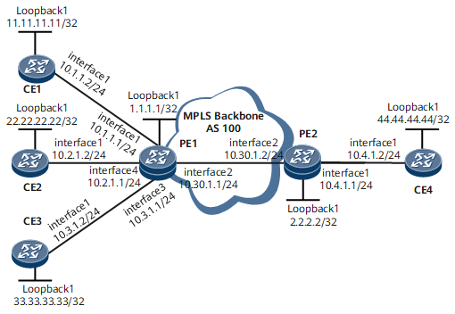
Figure 1 shows the networking of a BGP/MPLS IP VPN. CE1, CE2, CE3, and CE4 belong to vpna; CE1, CE2, CE3 and PE1 are in the same AS and all these three CEs are connected to PE1. It is required that PE1 be configured as an RR to reduce the number of IBGP connections between CE1, CE2, and CE3 and reflect private routes.

Configuration Notes
When configuring an RR for the optimization of the VPN access layer, note the following:
The interfaces that connect PE1 to CE1, CE2, and CE3 are bound to the same VPN instance.
PE1, CE1, CE2, and CE3 are in the same AS.
An IBGP connection is set up between PE1 and each of CE1, CE2, and CE3, and direct routes of PE1 are imported to the BGP VPN instance IPv4 address family so that routes from a CE can recurse to the next hop when being reflected to other CEs.
Configuration Roadmap
The configuration roadmap is as follows:
Configure a basic BGP/MPLS IP VPN.
Set up an IBGP connection between PE1 and each of CE1, CE2, and CE3.
Configure PE1 as an RR to reflect routes from each CE.
Data Preparation
To complete the configuration, you need the following data:
MPLS LSR IDs of PEs
Names, RDs, and VPN targets of the VPN instances on PE1 and PE2
AS numbers of the PEs and CEs
Procedure
- Configure an IGP on the MPLS backbone network so that the PEs can learn the routes to each other's loopback interface. For configuration details, see Configuration Files in this section.
- Set up an LSP on the MPLS backbone network.
Enable MPLS and MPLS LDP on the devices and interfaces along the LSP. For configuration details, see Configuration Files in this section.
After completing the configurations, run the display mpls ldp session command on PEs. The command output shows that the Status field is Operational.
The following example uses the command output on PE1.
<PE1> display mpls ldp session LDP Session(s) in Public Network Codes: LAM(Label Advertisement Mode), SsnAge Unit(DDD:HH:MM) An asterisk (*) before a session means the session is being deleted. ------------------------------------------------------------------------- Peer-ID Status LAM SsnRole SsnAge KA-Sent/Rcv -------------------------------------------------------------------------- 2.2.2.2:0 Operational DU Passive 011:19:20 67949/67949 -------------------------------------------------------------------------- TOTAL: 1 Session(s) Found. LAM : Label Advertisement Mode SsnAge Unit : DDD:HH:MM - Set up an MP-IBGP peer relationship between PEs.
# Configure PE1.
[~PE1] bgp 100
[*PE1-bgp] peer 2.2.2.2 as-number 100
[*PE1-bgp] peer 2.2.2.2 connect-interface loopback 1
[*PE1-bgp] ipv4-family vpnv4
[*PE1-bgp-af-vpnv4] peer 2.2.2.2 enable
[*PE1-bgp-af-vpnv4] commit
[*PE1-bgp-af-vpnv4] quit
[~PE1-bgp] quit
# Configure PE2.
[~PE2] bgp 100
[*PE2-bgp] peer 1.1.1.1 as-number 100
[*PE2-bgp] peer 1.1.1.1 connect-interface loopback 1
[*PE2-bgp] ipv4-family vpnv4
[*PE2-bgp-af-vpnv4] peer 1.1.1.1 enable
[*PE2-bgp-af-vpnv4] commit
[~PE2-bgp-af-vpnv4] quit
[~PE2-bgp] quit
After completing the configurations, run the display bgp vpnv4 all peer command on PEs. The command output shows that MP-IBGP peer relationships have been established between PEs and CEs.
<PE1> display bgp vpnv4 all peer
 BGP local router ID : 1.1.1.1
 Local AS number : 100
 Total number of peers : 1         Peers in established state : 1

  Peer            V          AS  MsgRcvd  MsgSent  OutQ  Up/Down       State  PrefRcv

  2.2.2.2         4         100     1633     1641     0 27:09:46 Established   0
- Configure an IPv4-address-family-supporting VPN instance on each PE and bind the interface that connects a PE to a CE to the VPN instance on that PE.
# Configure PE1.
[~PE1] ip vpn-instance vpna
[*PE1-vpn-instance-vpna] ipv4-family
[*PE1-vpn-instance-vpna-af-ipv4] route-distinguisher 100:1
[*PE1-vpn-instance-vpna-af-ipv4] vpn-target 111:1 both
[*PE1-vpn-instance-vpna-af-ipv4] quit
[*PE1-vpn-instance-vpna] quit
[*PE1] interface gigabitethernet 0/1/0
[*PE1-GigabitEthernet0/1/0] ip binding vpn-instance vpna
[*PE1-GigabitEthernet0/1/0] ip address 10.1.1.1 24
[*PE1-GigabitEthernet0/1/0] quit
[*PE1] interface gigabitethernet 0/1/24
[*PE1-GigabitEthernet0/1/24] ip binding vpn-instance vpna
[*PE1-GigabitEthernet0/1/24] ip address 10.2.1.1 24
[*PE1-GigabitEthernet0/1/24] quit
[*PE1] interface gigabitethernet 0/1/16
[*PE1-GigabitEthernet0/1/16] ip binding vpn-instance vpna
[*PE1-GigabitEthernet0/1/16] ip address 10.3.1.1 24
[~PE1-GigabitEthernet0/1/16] quit
[~PE1] commit
# Configure PE2.
[~PE2] ip vpn-instance vpna
[*PE2-vpn-instance-vpna] ipv4-family
[*PE2-vpn-instance-vpna-af-ipv4] route-distinguisher 200:1
[*PE2-vpn-instance-vpna-af-ipv4] vpn-target 111:1 both
[*PE2-vpn-instance-vpna-af-ipv4] quit
[*PE2-vpn-instance-vpna] quit
[*PE2] interface gigabitethernet 0/1/0
[*PE2-GigabitEthernet0/1/0] ip binding vpn-instance vpna
[*PE2-GigabitEthernet0/1/0] ip address 10.4.1.1 24
[*PE2-GigabitEthernet0/1/0] quit
[*PE2] commit
# After completing the configurations, run the display ip vpn-instance verbose command on PEs to check the configurations of VPN instances.
The following example uses the command output on PE1.
<PE1> display ip vpn-instance verbose
 Total VPN-Instances configured : 1
Total IPv4 VPN-Instances configured : 1
Total IPv6 VPN-Instances configured : 0

 VPN-Instance Name and ID : vpna, 1
  Interfaces : GigabitEthernet0/1/0,
               GigabitEthernet0/1/24,
               GigabitEthernet0/1/16
 Address family ipv4
  Create date : 2009/12/06 15:39:50
  Up time : 0 days, 00 hours, 02 minutes and 22 seconds
  Vrf Status : UP
  Route Distinguisher : 100:1
  Export VPN Targets :  111:1
  Import VPN Targets :  111:1
  Label policy : label per route
  The diffserv-mode Information is : uniform
  The ttl-mode Information is : pipe
- Set up an IBGP peer relationship between PE1 and each of CE1, CE2, and CE3.
# Configure PE1 as an IBGP peer for each of CE1, CE2, and CE3, and import direct routes to the BGP VPN instance IPv4 address family routing table of PE1.
[~PE1] bgp 100
[*PE1-bgp] ipv4-family vpn-instance vpna
[*PE1-bgp-vpna] peer 10.1.1.2 as-number 100
[*PE1-bgp-vpna] peer 10.2.1.2 as-number 100
[*PE1-bgp-vpna] peer 10.3.1.2 as-number 100
[*PE1-bgp-vpna] import-route direct
[*PE1-bgp-vpna] commit
[~PE1-bgp-vpna] quit
# Configure CE1.
[~CE1] interface loopback 1
[*CE1-Loopback1] ip address 11.11.11.11 32
[*CE1-Loopback1] quit
[*CE1] bgp 100
[*CE1-bgp] peer 10.1.1.1 as-number 100
[*CE1-bgp] network 11.11.11.11 32
[~CE1-bgp] commit
# Configure CE2.
[~CE2] interface loopback 1
[*CE2-Loopback1] ip address 22.22.22.22 32
[*CE2-Loopback1] quit
[*CE2] bgp 100
[*CE2-bgp] peer 10.2.1.1 as-number 100
[*CE2-bgp] network 22.22.22.22 32
[~CE2-bgp] commit
# Configure CE3.
[~CE3] interface loopback 1
[*CE3-Loopback1] ip address 33.33.33.33 32
[*CE3-Loopback1] quit
[*CE3] bgp 100
[*CE3-bgp] peer 10.3.1.1 as-number 100
[*CE3-bgp] network 33.33.33.33 32
[~CE3-bgp] commit
After completing the configurations, run the display bgp vpnv4 vpn-instance peer command on PE1. The command output shows that the IBGP peer relationship is set up between PE1 and each of CE1, CE2, and CE3.
<PE1> display bgp vpnv4 vpn-instance vpna peer

 BGP local router ID : 10.1.1.1
 Local AS number : 100
 Total number of peers : 3         Peers in established state : 3

  Peer            V          AS  MsgRcvd  MsgSent  OutQ  Up/Down       State  PrefRcv
  10.1.1.2        4         100     1058     1058     0 17:37:22 Established    0
  10.2.1.2        4         100        3        3     0 00:01:56 Established    0
  10.3.1.2        4         100        2        2     0 00:00:32 Established    0
- Configure route reflection on PE1.
# Configure PE1.
[~PE1] bgp 100
[*PE1-bgp] ipv4-family vpn-instance vpna
[*PE1-bgp-vpna] peer 10.1.1.2 reflect-client
[*PE1-bgp-vpna] peer 10.2.1.2 reflect-client
[*PE1-bgp-vpna] peer 10.3.1.2 reflect-client
[*PE1-bgp-vpna] commit
- Verify the configuration.
Run the display ip routing-table command on each CE. The command output shows that there are routes to the loopback interfaces of the other CEs. The following example uses the command output on CE2.
<CE2> display ip routing-table
Route Flags: R - relay, D - download to fib, T - to vpn-instance, B - black hole route
------------------------------------------------------------------------------
Routing Table : _public_
         Destinations : 15       Routes : 15

Destination/Mask    Proto  Pre  Cost        Flags NextHop         Interface

       10.1.1.0/24  BGP    255  0             RD 10.2.1.1        GigabitEthernet0/1/0
       10.1.1.1/32  BGP    255  0             RD 10.1.1.2        GigabitEthernet0/1/0
       10.1.1.2/32  BGP    255  0             RD 10.2.1.1        GigabitEthernet0/1/0
       10.2.1.0/24  Direct 0    0             D  10.2.1.2        GigabitEthernet0/1/0
       10.2.1.2/32  Direct 0    0             D  127.0.0.1       GigabitEthernet0/1/0
     10.2.1.255/32  Direct 0    0             D  127.0.0.1       GigabitEthernet0/1/0
       10.3.1.0/24  BGP    255  0             RD 10.2.1.1        GigabitEthernet0/1/0
   11.11.11.11/32  EBGP   255  0             RD 10.1.1.2        GigabitEthernet0/1/0
   22.22.22.22/32  Direct 0    0             D  127.0.0.1       GigabitEthernet0/1/0
   33.33.33.33/32  EBGP   255  0             RD 10.3.1.2        GigabitEthernet0/1/0
   44.44.44.44/32  EBGP   255  0             RD 10.2.1.1        GigabitEthernet0/1/0
      127.0.0.0/8   Direct 0    0             D  127.0.0.1       InLoopBack0
      127.0.0.1/32  Direct 0    0             D  127.0.0.1       InLoopBack0
127.255.255.255/32  Direct 0    0             D  127.0.0.1       InLoopBack0
255.255.255.255/32  Direct 0    0             D  127.0.0.1       InLoopBack0
Configuration Files
CE1 configuration file
#
 sysname CE1
#
interface GigabitEthernet0/1/0
 undo shutdown
 ip address 10.1.1.2 255.255.255.0
#
interface LoopBack1
 ip address 11.11.11.11 255.255.255.255
#
 bgp 100
 peer 10.1.1.1 as-number 100
 #
 ipv4-family unicast
  undo synchronization
  peer 10.1.1.1 enable
  network 11.11.11.11 255.255.255.255
#
return
CE2 configuration file
#
 sysname CE2
#
interface GigabitEthernet0/1/0
 undo shutdown
 ip address 10.2.1.2 255.255.255.0
#
interface LoopBack1
 ip address 22.22.22.22 255.255.255.255
#
bgp 100
 peer 10.2.1.1 as-number 100
 #
 ipv4-family unicast
  undo synchronization
  peer 10.2.1.1 enable
  network 22.22.22.22 255.255.255.255
#
return
CE3 configuration file
#
 sysname CE3
#
interface GigabitEthernet0/1/0
 undo shutdown
 ip address 10.3.1.2 255.255.255.0
#
interface LoopBack1
 ip address 33.33.33.33 255.255.255.255
#
bgp 100
 peer 10.3.1.1 as-number 100
 network 33.33.33.33 255.255.255.255
 #
 ipv4-family unicast
  undo synchronization
  peer 10.3.1.1 enable
#
return
PE1 configuration file
#
 sysname PE1
#
mpls lsr-id 1.1.1.1
#
mpls
#
mpls ldp
#
interface GigabitEthernet0/1/0
 undo shutdown
 ip binding vpn-instance vpna
 ip address 10.1.1.1 255.255.255.0
#
interface GigabitEthernet0/1/24
 undo shutdown
 ip binding vpn-instance vpna
 ip address 10.2.1.1 255.255.255.0
#
interface GigabitEthernet0/1/16
 undo shutdown
 ip binding vpn-instance vpna
 ip address 10.3.1.1 255.255.255.0
#
interface GigabitEthernet0/1/8
 undo shutdown
 mpls
 mpls ldp
 ip address 10.30.1.1 255.255.255.0
#
interface LoopBack1
 undo shutdown
 ip address 1.1.1.1 255.255.255.255
#
ip vpn-instance vpna
 ipv4-family
  route-distinguisher 100:1
  apply-label per-instance
  vpn-target 111:1 export-extcommunity
  vpn-target 111:1 import-extcommunity
#
ospf 1
 area 0.0.0.0
  network 1.1.1.1 0.0.0.0
  network 10.30.1.0 0.0.0.255
#
bgp 100
 peer 2.2.2.2 as-number 100
 peer 2.2.2.2 connect-interface LoopBack1
 #
 ipv4-family unicast
  undo synchronization
  peer 2.2.2.2 enable
 #
 ipv4-family vpnv4
  policy vpn-target
  peer 2.2.2.2 enable
 #
 ipv4-family vpn-instance vpna
  peer 10.1.1.2 as-number 100
  peer 10.2.1.2 as-number 100
  peer 10.3.1.2 as-number 100
  peer 10.1.1.2 reflect-client
  peer 10.2.1.2 reflect-client
  peer 10.3.1.2 reflect-client
  import-route direct
#
return
PE2 configuration file
#
 sysname PE2
#
mpls lsr-id 2.2.2.2
#
mpls
#
mpls ldp
#
interface GigabitEthernet0/1/0
 undo shutdown
 ip binding vpn-instance vpna
 ip address 10.4.1.1 255.255.255.0
#
interface GigabitEthernet0/1/8
 undo shutdown
 mpls
 mpls ldp
 ip address 10.30.1.2 255.255.255.0
#
interface LoopBack1
 undo shutdown
 ip address 2.2.2.2 255.255.255.255
#
ip vpn-instance vpna
 ipv4-family
  route-distinguisher 100:1
  apply-label per-instance
  vpn-target 111:1 export-extcommunity
  vpn-target 111:1 import-extcommunity
#
ospf 1
 area 0.0.0.0
  network 2.2.2.2 0.0.0.0
  network 10.30.1.0 0.0.0.255
#
bgp 100
 peer 1.1.1.1 as-number 100
 peer 1.1.1.1 connect-interface LoopBack1
 #
 ipv4-family unicast
  undo synchronization
  peer 1.1.1.1 enable
 #
 ipv4-family vpnv4
  policy vpn-target
  peer 1.1.1.1 enable
 #
 ipv4-family vpn-instance vpna
  peer 10.4.1.2 as-number 65410
#
return
CE4 configuration file
#
 sysname CE4
#
interface GigabitEthernet0/1/0
 undo shutdown
 ip address 10.4.1.2 255.255.255.0
#
interface LoopBack1
 ip address 44.44.44.44 255.255.255.255
#
bgp 65410
 peer 10.4.1.1 as-number 100
 network 44.44.44.44 255.255.255.255
 #
 ipv4-family unicast
  undo synchronization
  peer 10.4.1.1 enable
#
return