Example for Configuring Hub and Spoke (Dual Links Between a Hub-PE and a Hub-CE)
In hub and spoke networking, an access control device is specified in the VPN, and users communicate with each other through the access control device.
Networking Requirements
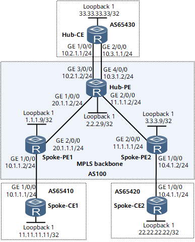
On the network shown in Figure 1, the communications between the Spoke-CEs is controlled by the Hub-CE at a central site. In other words, the traffic between Spoke-CEs is forwarded through the Hub-CE, not only through the Hub-PE.
Configuration Notes
When configuring hub and spoke, note the following:
The import target and export target configured on a Spoke-PE are different.
Two VPN instances (vpn_in and vpn_out) are created on the Hub-PE. The VPN targets received by vpn_in are the VPN targets advertised by the two Spoke-PEs; the VPN targets advertised by vpn_out are the VPN targets received by the two Spoke-PEs and are different from the VPN targets received by vpn_in.
The Hub-PE is configured to accept the routes whose AS number is repeated once in the AS_Path attribute.
Configuration Roadmap
The configuration roadmap is as follows:
Establish MP-IBGP peer relationships between the Hub-PE and Spoke-PEs. There is no need to establish an MP-IBGP peer relationship or exchange VPN route information between the two Spoke-PEs.
Configure VPN instances and VPN targets on PEs.
Configure EBGP connections between CEs and PEs.
Data Preparation
To complete the configuration, you need the following data:
MPLS LSR ID of each PE
Names, RDs, and VPN targets of the VPN instances on the Hub-PE and Spoke-PEs
Procedure
- Configure an IGP on the MPLS backbone network for the interworking between the Hub-PE and Spoke-PEs.
This example uses OSPF as the IGP. For configuration details, see Configuration Files in this section.
After the configurations are complete, OSPF neighbor relationships are set up between the Hub-PE and Spoke-PEs. Run the display ospf peer command. The command output shows that the neighbor status is Full. Run the display ip routing-table command. The command output shows that the Hub-PE and Spoke-PEs have learned the routes to each other's loopback interface.
- Configure MPLS and MPLS LDP both globally and per interface on each node of the backbone network and set up LDP LSPs.
For configuration details, see Configuration Files in this section.
After the configurations are complete, LDP neighbor relationships are set up between the Hub-PE and Spoke-PEs. Run the display mpls ldp session command on routers. The command output shows that the Session State field is Operational.
- Configure an IPv4-address-family-supporting VPN instance on each PE and bind the interface that connects a PE to a CE to the VPN instance on that PE.

The import target of a VPN instance on the Hub-PE must contain the export target attributes of all Spoke-PEs.
The export target of a VPN instance on the Hub-PE must contain the import target attributes of all Spoke-PEs.
# Configure Spoke-PE1.
<Spoke-PE1> system-view
[~Spoke-PE1] ip vpn-instance vpna
[*Spoke-PE1-vpn-instance-vpna] ipv4-family
[*Spoke-PE1-vpn-instance-vpna-af-ipv4] route-distinguisher 100:1
[*Spoke-PE1-vpn-instance-vpna-af-ipv4] vpn-target 100:1 export-extcommunity
[*Spoke-PE1-vpn-instance-vpna-af-ipv4] vpn-target 200:1 import-extcommunity
[*Spoke-PE1-vpn-instance-vpna-af-ipv4] commit
[*Spoke-PE1-vpn-instance-vpna-af-ipv4] quit
[*Spoke-PE1] interface gigabitethernet 0/1/0
[*Spoke-PE1-GigabitEthernet0/1/0] ip binding vpn-instance vpna
[*Spoke-PE1-GigabitEthernet0/1/0] ip address 10.1.1.2 24
[*Spoke-PE1-GigabitEthernet0/1/0] commit
[*Spoke-PE1-GigabitEthernet0/1/0] quit
# Configure Spoke-PE2.
<Spoke-PE2> system-view
[~Spoke-PE2] ip vpn-instance vpna
[*Spoke-PE2-vpn-instance-vpna] ipv4-family
[*Spoke-PE2-vpn-instance-vpna-af-ipv4] route-distinguisher 100:3
[*Spoke-PE2-vpn-instance-vpna-af-ipv4] vpn-target 100:1 export-extcommunity
[*Spoke-PE2-vpn-instance-vpna-af-ipv4] vpn-target 200:1 import-extcommunity
[*Spoke-PE2-vpn-instance-vpna-af-ipv4] commit
[*Spoke-PE2-vpn-instance-vpna-af-ipv4] quit
[*Spoke-PE2] interface gigabitethernet 0/1/0
[*Spoke-PE2-GigabitEthernet0/1/0] ip binding vpn-instance vpna
[*Spoke-PE2-GigabitEthernet0/1/0] ip address 10.4.1.2 24
[*Spoke-PE2-GigabitEthernet0/1/0] commit
[~Spoke-PE2-GigabitEthernet0/1/0] quit
# Configure the Hub-PE.
[~Hub-PE] ip vpn-instance vpn_in
[*Hub-PE-vpn-instance-vpn_in] ipv4-family
[*Hub-PE-vpn-instance-vpn_in-af-ipv4] route-distinguisher 100:21
[*Hub-PE-vpn-instance-vpn_in-af-ipv4] vpn-target 100:1 import-extcommunity
[*Hub-PE-vpn-instance-vpn_in-af-ipv4] commit
[*Hub-PE-vpn-instance-vpn_in-af-ipv4] quit
[*Hub-PE-vpn-instance-vpn_in] quit
[*Hub-PE] ip vpn-instance vpn_out
[*Hub-PE-vpn-instance-vpn_out] ipv4-family
[*Hub-PE-vpn-instance-vpn_out-af-ipv4] route-distinguisher 100:22
[*Hub-PE-vpn-instance-vpn_out-af-ipv4] vpn-target 200:1 export-extcommunity
[*Hub-PE-vpn-instance-vpn_out-af-ipv4] commit
[*Hub-PE-vpn-instance-vpn_out-af-ipv4] quit
[*Hub-PE-vpn-instance-vpn_out] quit
[*Hub-PE] interface gigabitethernet 0/1/16
[*Hub-PE-GigabitEthernet0/1/16] ip binding vpn-instance vpn_in
[*Hub-PE-GigabitEthernet0/1/16] ip address 10.2.1.2 24
[*Hub-PE-GigabitEthernet0/1/16] commit
[*Hub-PE-GigabitEthernet0/1/16] quit
[*Hub-PE] interface gigabitethernet 0/1/24
[*Hub-PE-GigabitEthernet0/1/24] ip binding vpn-instance vpn_out
[*Hub-PE-GigabitEthernet0/1/24] ip address 10.3.1.2 24
[*Hub-PE-GigabitEthernet0/1/24] commit
[~Hub-PE-GigabitEthernet0/1/24] quit
# Assign an IP address to each interface on CEs, as shown in Figure 1. For configuration details, see Configuration Files in this section.
After completing the configurations, run the display ip vpn-instance verbose command on PEs to view the configurations of VPN instances. Each PE can ping its connected CEs using the ping -vpn-instance vpn-name ip-address command.
If a PE has multiple interfaces bound to the same VPN instance, you must specify a source IP address by specifying -a source-ip-address in the ping -vpn-instance vpn-instance-name -a source-ip-address dest-ip-address command to ping the CE connected to the remote PE. Otherwise, the ping operation fails.
- Set up EBGP peer relationships between PEs and CEs to import VPN routes.
Configure the Hub-PE to allow the AS number to be repeated once in the AS_Path attribute to receive the routes advertised by the Hub-CE.
You do not need to configure the Spoke-PEs to allow the AS number to be repeated once because the router does not check the AS-Path attributes in its received routes advertised by the IBGP peer.
# Configure Spoke-CE1.
[~Spoke-CE1] interface loopback 1
[*Spoke-CE1-Loopback1] ip address 11.11.11.11 32
[*Spoke-CE1-Loopback1] quit
[*Spoke-CE1] bgp 65410
[*Spoke-CE1-bgp] peer 10.1.1.2 as-number 100
[*Spoke-CE1-bgp] network 11.11.11.11 32
[*Spoke-CE1-bgp] quit
[*Spoke-CE1] commit
# Configure Spoke-PE1.
[~Spoke-PE1] bgp 100
[*Spoke-PE1-bgp] ipv4-family vpn-instance vpna
[*Spoke-PE1-bgp-vpna] peer 10.1.1.1 as-number 65410
[*Spoke-PE1-bgp-vpna] commit
[~Spoke-PE1-bgp-vpna] quit
[~Spoke-PE1-bgp] quit
# Configure Spoke-CE2.
[~Spoke-CE2] interface loopback 1
[*Spoke-CE2-Loopback1] ip address 22.22.22.22 32
[*Spoke-CE2-Loopback1] quit
[*Spoke-CE2] bgp 65420
[*Spoke-CE2-bgp] peer 10.4.1.2 as-number 100
[*Spoke-CE2-bgp] network 22.22.22.22 32
[*Spoke-CE2-bgp] commit
[~Spoke-CE2-bgp] quit
# Configure Spoke-PE2.
[~Spoke-PE2] bgp 100
[*Spoke-PE2-bgp] ipv4-family vpn-instance vpna
[*Spoke-PE2-bgp-vpna] peer 10.4.1.1 as-number 65420
[*Spoke-PE2-bgp-vpna] commit
[~Spoke-PE2-bgp-vpna] quit
[~Spoke-PE2-bgp] quit
# Configure the Hub-CE.
[~Hub-CE] interface loopback 1
[*Hub-CE-Loopback1] ip address 33.33.33.33 32
[*Hub-CE-Loopback1] quit
[*Hub-CE] bgp 65430
[*Hub-CE-bgp] peer 10.2.1.2 as-number 100
[*Hub-CE-bgp] peer 10.3.1.2 as-number 100
[*Hub-CE-bgp] network 33.33.33.33 32
[*Hub-CE-bgp] quit
[*Hub-CE] commit
# Configure the Hub-PE.
[~Hub-PE] bgp 100
[*Hub-PE-bgp] ipv4-family vpn-instance vpn_in
[*Hub-PE-bgp-vpn_in] peer 10.2.1.1 as-number 65430
[*Hub-PE-bgp-vpn_in] commit
[*Hub-PE-bgp-vpn_in] quit
[*Hub-PE-bgp] ipv4-family vpn-instance vpn_out
[*Hub-PE-bgp-vpn_out] peer 10.3.1.1 as-number 65430
[*Hub-PE-bgp-vpn_out] peer 10.3.1.1 allow-as-loop 1
[*Hub-PE-bgp-vpn_out] commit
[~Hub-PE-bgp-vpn_out] quit
[~Hub-PE-bgp] quit
After completing the configurations, run the display bgp vpnv4 all peer command on PEs. The command output shows that BGP peer relationships have been established between PEs and CEs.
- Set up an MP-IBGP peer relationship between PEs.
# Configure Spoke-PE1.
[~Spoke-PE1] bgp 100
[~Spoke-PE1-bgp] peer 2.2.2.9 as-number 100
[*Spoke-PE1-bgp] peer 2.2.2.9 connect-interface loopback 1
[*Spoke-PE1-bgp] ipv4-family vpnv4
[*Spoke-PE1-bgp-af-vpnv4] peer 2.2.2.9 enable
[*Spoke-PE1-bgp-af-vpnv4] commit
[~Spoke-PE1-bgp-af-vpnv4] quit
# Configure Spoke-PE2.
[~Spoke-PE2] bgp 100
[~Spoke-PE2-bgp] peer 2.2.2.9 as-number 100
[*Spoke-PE2-bgp] peer 2.2.2.9 connect-interface loopback 1
[*Spoke-PE2-bgp] ipv4-family vpnv4
[*Spoke-PE2-bgp-af-vpnv4] peer 2.2.2.9 enable
[*Spoke-PE2-bgp-af-vpnv4] commit
[~Spoke-PE2-bgp-af-vpnv4] quit
# Configure the Hub-PE.
[~Hub-PE] bgp 100
[~Hub-PE-bgp] peer 1.1.1.9 as-number 100
[*Hub-PE-bgp] peer 1.1.1.9 connect-interface loopback 1
[*Hub-PE-bgp] peer 3.3.3.9 as-number 100
[*Hub-PE-bgp] peer 3.3.3.9 connect-interface loopback 1
[*Hub-PE-bgp] ipv4-family vpnv4
[*Hub-PE-bgp-af-vpnv4] peer 1.1.1.9 enable
[*Hub-PE-bgp-af-vpnv4] peer 3.3.3.9 enable
[*Hub-PE-bgp-af-vpnv4] commit
[~Hub-PE-bgp-af-vpnv4] quit
After completing the configurations, run the display bgp peer or display bgp vpnv4 all peer command on PEs. The command output shows that BGP peer relationships have been established between PEs.
- Verify the configuration.
After the configurations are complete, the Spoke-CEs can successfully ping each other. Run the tracert command. The command output shows that the traffic between the Spoke-CEs is forwarded through the Hub-CE. You can also deduce the number of forwarding devices between the Spoke-CEs based on the TTL displayed in the ping command output.
The following example uses the command output on Spoke-CE1.
<Spoke-CE1> ping -a 11.11.11.11 22.22.22.22
  PING 22.22.22.22: 56  data bytes, press CTRL_C to break
    Reply from 22.22.22.22: bytes=56 Sequence=1 ttl=250ime=80 ms
    Reply from 22.22.22.22: bytes=56 Sequence=2 ttl=250ime=129 ms
    Reply from 22.22.22.22: bytes=56 Sequence=3 ttl=250 time=132 ms
    Reply from 22.22.22.22: bytes=56 Sequence=4 ttl=250 time=92 ms
    Reply from 22.22.22.22: bytes=56 Sequence=5 ttl=250 time=126 ms
  --- 22.22.22.22 ping statistics ---
    5 packet(s) transmitted
    5 packet(s) received
    0.00% packet loss
    round-trip min/avg/max = 80/111/132 ms
<Spoke-CE1> tracert -a 11.11.11.11 22.22.22.22
 traceroute to  22.22.22.22(22.22.22.22), max hops: 30 ,packet length: 40
1 10.1.1.2 8 ms  2 ms  2 ms
 2 10.2.1.2 < AS=100 > 3 ms  2 ms  2 ms
 3 10.2.1.1 < AS=100 > 3 ms  2 ms  2 ms
 4 10.3.1.2 < AS=65430 > 3 ms  2 ms  2 ms
 5 10.4.1.2 < AS=100 > 6 ms  6 ms  6 ms
 6 22.22.22.22 < AS=65420 > 6 ms  6 ms  6 ms
Run the display bgp routing-table command on each Spoke-CE. The command output shows that there are repetitive AS numbers in the AS-Path attributes of the BGP routes to the peer Spoke-CE.
The following example uses the command output on Spoke-CE1.
<Spoke-CE1> display bgp routing-table
 BGP Local router ID is 11.11.11.11
 Status codes: * - valid, > - best, d - damped, x - best external, a - add path,
              h - history,  i - internal, s - suppressed, S - Stale
              Origin : i - IGP, e - EGP, ? - incomplete
 Total Number of Routes: 5
     Network         NextHop      MED    LocPrf    PrefVal Path/Ogn
 *>  10.1.1.0/24     0.0.0.0       0                 0      ?
 *                   10.1.1.2      0                 0      100?
 *>  10.1.1.1/32     0.0.0.0       0                 0      ?
 *>33.33.33.33/32    10.1.1.2                        0      100 65430?
 *>  22.22.22.22/32    10.1.1.2                         0      100 65430 100 65420?
Configuration Files
Spoke-CE1 configuration file
#
 sysname Spoke-CE1
#
interface GigabitEthernet0/1/0
 undo shutdown
 ip address 100.1.1.1 255.255.255.0
#
interface Loopback 1
 undo shutdown
 ip address 11.11.11.11 255.255.255.255
#
bgp 65410
 peer 100.1.1.2 as-number 100
 #
 ipv4-family unicast
  undo synchronization
  peer 100.1.1.2 enable
  network 11.11.11.11 255.255.255.255
#
return
Spoke-PE1 configuration file
#
 sysname Spoke-PE1
#
ip vpn-instance vpna
 ipv4-family
  route-distinguisher 100:1
  apply-label per-instance
  vpn-target 100:1 export-extcommunity
  vpn-target 200:1 import-extcommunity
#
mpls lsr-id 1.1.1.9
#
mpls
#
mpls ldp
#
interface GigabitEthernet0/1/0
 undo shutdown
 ip binding vpn-instance vpna
 ip address 100.1.1.2 255.255.255.0
#
interface GigabitEthernet0/1/8
 undo shutdown
 ip address 20.1.1.1 255.255.255.0
 mpls
 mpls ldp
#
interface LoopBack1
 ip address 1.1.1.9 255.255.255.255
#
bgp 100
 peer 2.2.2.9 as-number 100
 peer 2.2.2.9 connect-interface LoopBack1
 #
 ipv4-family unicast
  undo synchronization
  peer 2.2.2.9 enable
 #
 ipv4-family vpnv4
  policy vpn-target
  peer 2.2.2.9 enable
#
 ipv4-family vpn-instance vpna
  peer 100.1.1.1 as-number 65410
#
ospf 1
 area 0.0.0.0
  network 20.1.1.0 0.0.0.255
  network 1.1.1.9 0.0.0.0
#
return
Spoke-PE2 configuration file
#
 sysname Spoke-PE2
#
ip vpn-instance vpna
 ipv4-family
  route-distinguisher 100:3
  apply-label per-instance
  vpn-target 100:1 export-extcommunity
  vpn-target 200:1 import-extcommunity
#
mpls lsr-id 3.3.3.9
#
mpls
#
mpls ldp
#
interface GigabitEthernet0/1/0
 undo shutdown
 ip binding vpn-instance vpna
 ip address 10.4.1.2 255.255.255.0
#
interface GigabitEthernet0/1/8
 undo shutdown
 ip address 11.1.1.1 255.255.255.0
 mpls
 mpls ldp
#
interface LoopBack1
 ip address 3.3.3.9 255.255.255.255
#
bgp 100
 peer 2.2.2.9 as-number 100
 peer 2.2.2.9 connect-interface LoopBack1
 #
 ipv4-family unicast
  undo synchronization
  peer 2.2.2.9 enable
 #
 ipv4-family vpnv4
  policy vpn-target
  peer 2.2.2.9 enable
#
 ipv4-family vpn-instance vpna
  peer 10.4.1.1 as-number 65420
#
ospf 1
 area 0.0.0.0
  network 3.3.3.9 0.0.0.0
  network 11.1.1.0 0.0.0.255
#
return
Spoke-CE2 configuration file
#
 sysname Spoke-CE2
#
interface GigabitEthernet0/1/0
 undo shutdown
 ip address 10.4.1.1 255.255.255.0
#
interface Loopback 1
 undo shutdown
 ip address 22.22.22.22 255.255.255.255
#
bgp 65420
 peer 10.4.1.2 as-number 100
 #
 ipv4-family unicast
  undo synchronization
  peer 10.4.1.2 enable
  network 22.22.22.22 255.255.255.255
#
return
Hub-CE configuration file
#
 sysname Hub-CE
#
interface GigabitEthernet0/1/0
 undo shutdown
 ip address 10.2.1.1 255.255.255.0
#
interface GigabitEthernet0/1/8
 undo shutdown
 ip address 10.3.1.1 255.255.255.0
#
interface Loopback 1
 undo shutdown
 ip address 33.33.33.33 255.255.255.255
#
bgp 65430
 peer 10.2.1.2 as-number 100
 peer 10.3.1.2 as-number 100
 network 33.33.33.33 255.255.255.255
 #
 ipv4-family unicast
  undo synchronization
  peer 10.3.1.2 enable
  peer 10.2.1.2 enable
#
return
Hub-PE configuration file
#
 sysname Hub-PE
#
ip vpn-instance vpn_in
 ipv4-family
  route-distinguisher 100:21
  apply-label per-instance
  vpn-target 100:1 import-extcommunity
#
ip vpn-instance vpn_out
 ipv4-family
  route-distinguisher 100:22
  apply-label per-instance
  vpn-target 200:1 export-extcommunity
#
mpls lsr-id 2.2.2.9
#
mpls
#
mpls ldp
#
interface GigabitEthernet0/1/0
 undo shutdown
 ip address 20.1.1.2 255.255.255.0
 mpls
 mpls ldp
#
interface GigabitEthernet0/1/8
 undo shutdown
 ip address 11.1.1.2 255.255.255.0
 mpls
 mpls ldp
#
interface GigabitEthernet0/1/16
 undo shutdown
 ip binding vpn-instance vpn_in
 ip address 10.2.1.2 255.255.255.0
#
interface GigabitEthernet0/1/24
 undo shutdown
 ip binding vpn-instance vpn_out
 ip address 10.3.1.2 255.255.255.0
#
interface LoopBack1
 ip address 2.2.2.9 255.255.255.255
#
bgp 100
 peer 1.1.1.9 as-number 100
 peer 1.1.1.9 connect-interface LoopBack1
 peer 3.3.3.9 as-number 100
 peer 3.3.3.9 connect-interface LoopBack1
 #
 ipv4-family unicast
  undo synchronization
  peer 1.1.1.9 enable
  peer 3.3.3.9 enable
 #
 ipv4-family vpnv4
  policy vpn-target
  peer 1.1.1.9 enable
  peer 3.3.3.9 enable
#
 ipv4-family vpn-instance vpn_in
  peer 10.2.1.1 as-number 65430
#
 ipv4-family vpn-instance vpn_out
  peer 10.3.1.1 as-number 65430
  peer 10.3.1.1 allow-as-loop
#
ospf 1
 area 0.0.0.0
  network 2.2.2.9 0.0.0.0
  network 20.1.1.0 0.0.0.255
  network 11.1.1.0 0.0.0.255
#
return