Example for Configuring L3VPN over SR-MPLS TE
This section provides an example for configuring L3VPN over an SR-MPLS TE tunnel to ensure secure communication between users of the same VPN.
Networking Requirements
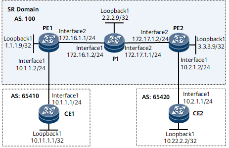
To ensure secure communication between CE1 and CE2, configure L3VPN over an SR-MPLS TE tunnel.
Precautions
When you configure L3VPN over an SR-MPLS TE tunnel, note the following:
After a PE interface connected to a CE is bound to a VPN instance, Layer 3 features, such as the IP address and routing protocol, on this interface are automatically deleted. These features can be reconfigured if required.
Configuration Roadmap
The configuration roadmap is as follows:
Configure IS-IS on the backbone network to ensure PE communication.
On the backbone network, enable MPLS, configure segment routing (SR), establish an SR-MPLS TE tunnel, specify the tunnel IP address, tunnel protocol, and destination IP address, and use explicit paths for path computation.
On each PE, configure a VPN instance, enable the IPv4 address family, and bind each PE interface that connects to a CE to the corresponding VPN instance.
Configure MP-IBGP between PEs to exchange VPN routing information.
Configure EBGP between CEs and PEs to exchange VPN routing information.
Procedure
- Configure an IP address for each interface.
# Configure PE1.
<HUAWEI> system-view
[~HUAWEI] sysname PE1
[*HUAWEI] commit
[~PE1] interface loopback 1
[*PE1-LoopBack1] ip address 1.1.1.9 32
[*PE1-LoopBack1] quit
[*PE1] interface gigabitethernet0/1/8
[*PE1-GigabitEthernet0/1/8] ip address 172.16.1.1 24
[*PE1-GigabitEthernet0/1/8] quit
[*PE1] commit
# Configure P1.
<HUAWEI> system-view
[~HUAWEI] sysname P1
[*HUAWEI] commit
[~P1] interface loopback 1
[*P1-LoopBack1] ip address 2.2.2.9 32
[*P1-LoopBack1] quit
[*P1] interface gigabitethernet0/1/0
[*P1-GigabitEthernet0/1/0] ip address 172.16.1.2 24
[*P1-GigabitEthernet0/1/0] quit
[*P1] interface gigabitethernet0/1/8
[*P1-GigabitEthernet0/1/8] ip address 172.17.1.1 24
[*P1-GigabitEthernet0/1/8] quit
[*P1] commit
# Configure PE2.
<HUAWEI> system-view
[~HUAWEI] sysname PE2
[*HUAWEI] commit
[~PE2] interface loopback 1
[*PE2-LoopBack1] ip address 3.3.3.9 32
[*PE2-LoopBack1] quit
[*PE2] interface gigabitethernet0/1/8
[*PE2-GigabitEthernet0/1/8] ip address 172.17.1.2 24
[*PE2-GigabitEthernet0/1/8] quit
[*PE2] commit
- Configure an IGP on the MPLS backbone network to ensure communication between the PEs and P1. IS-IS is used in this example.
# Configure PE1.
[~PE1] isis 1
[*PE1-isis-1] is-level level-2
[*PE1-isis-1] network-entity 10.0000.0000.0001.00
[*PE1-isis-1] quit
[*PE1] interface loopback 1
[*PE1-LoopBack1] isis enable 1
[*PE1-LoopBack1] quit
[*PE1] interface gigabitethernet0/1/8
[*PE1-GigabitEthernet0/1/8] isis enable 1
[*PE1-GigabitEthernet0/1/8] quit
[*PE1] commit
# Configure P1.
[~P1] isis 1
[*P1-isis-1] is-level level-2
[*P1-isis-1] network-entity 10.0000.0000.0002.00
[*P1-isis-1] quit
[*P1] interface loopback 1
[*P1-LoopBack1] isis enable 1
[*P1-LoopBack1] quit
[*P1] interface gigabitethernet0/1/0
[*P1-GigabitEthernet0/1/0] isis enable 1
[*P1-GigabitEthernet0/1/0] quit
[*P1] interface gigabitethernet0/1/8
[*P1-GigabitEthernet0/1/8] isis enable 1
[*P1-GigabitEthernet0/1/8] quit
[*P1] commit
# Configure PE2.
[~PE2] isis 1
[*PE2-isis-1] is-level level-2
[*PE2-isis-1] network-entity 10.0000.0000.0003.00
[*PE2-isis-1] quit
[*PE2] interface loopback 1
[*PE2-LoopBack1] isis enable 1
[*PE2-LoopBack1] quit
[*PE2] interface gigabitethernet0/1/8
[*PE2-GigabitEthernet0/1/8] isis enable 1
[*PE2-GigabitEthernet0/1/8] quit
[*PE2] commit
- Configure basic MPLS functions and enable MPLS TE on the backbone network.
# Configure PE1.
[~PE1] mpls lsr-id 1.1.1.9
[*PE1] mpls
[*PE1-mpls] mpls te
[*PE1-mpls] quit
[*PE1] commit
# Configure P1.
[~P1] mpls lsr-id 2.2.2.9
[*P1] mpls
[*P1-mpls] mpls te
[*P1-mpls] quit
[*P1] commit
# Configure PE2.
[~PE2] mpls lsr-id 3.3.3.9
[*PE2] mpls
[*PE2-mpls] mpls te
[*PE2-mpls] quit
[*PE2] commit
- On the backbone network, configure SR, establish an SR-MPLS TE tunnel, specify the tunnel IP address, tunnel protocol, and destination IP address, and use explicit paths for path computation.
# Configure PE1.
[~PE1] segment-routing
[*PE1-segment-routing] quit
[*PE1] isis 1
[*PE1-isis-1] cost-style wide
[*PE1-isis-1] traffic-eng level-2
[*PE1-isis-1] segment-routing mpls
[*PE1-isis-1] segment-routing global-block 16000 20000
[*PE1-isis-1] quit

The SRGB range varies according to the device. The range specified in this example is for reference only.
[*PE1] interface loopback 1
[*PE1-LoopBack1] isis prefix-sid absolute 16100
[*PE1-LoopBack1] quit
[*PE1] commit
[~PE1] explicit-path pe2
[*PE1-explicit-path-pe2] next sid label 16200 type prefix
[*PE1-explicit-path-pe2] next sid label 16300 type prefix
[*PE1-explicit-path-pe2] quit
[*PE1] interface tunnel1
[*PE1-Tunnel1] ip address unnumbered interface LoopBack1
[*PE1-Tunnel1] tunnel-protocol mpls te
[*PE1-Tunnel1] destination 3.3.3.9
[*PE1-Tunnel1] mpls te tunnel-id 1
[*PE1-Tunnel1] mpls te signal-protocol segment-routing
[*PE1-Tunnel1] mpls te path explicit-path pe2
[*PE1-Tunnel1] commit
[~PE1-Tunnel1] quit
# Configure P1.
[~P1] segment-routing
[*P1-segment-routing] quit
[*P1] isis 1
[*P1-isis-1] cost-style wide
[*P1-isis-1] traffic-eng level-2
[*P1-isis-1] segment-routing mpls
[*P1-isis-1] segment-routing global-block 16000 20000
[*P1-isis-1] quit
The SRGB range varies according to the device. The range specified in this example is for reference only.
[*P1] interface loopback 1
[*P1-LoopBack1] isis prefix-sid absolute 16200
[*P1-LoopBack1] quit
[*P1] commit
# Configure PE2.
[~PE2] segment-routing
[*PE2-segment-routing] quit
[*PE2] isis 1
[*PE2-isis-1] cost-style wide
[*PE2-isis-1] traffic-eng level-2
[*PE2-isis-1] segment-routing mpls
[*PE2-isis-1] segment-routing global-block 16000 20000
[*PE2-isis-1] quit
The SRGB range varies according to the device. The range specified in this example is for reference only.
[*PE2] interface loopback 1
[*PE2-LoopBack1] isis prefix-sid absolute 16300
[*PE2-LoopBack1] quit
[*PE2] commit
[~PE2] explicit-path pe1
[*PE2-explicit-path-pe1] next sid label 16200 type prefix
[*PE2-explicit-path-pe1] next sid label 16100 type prefix
[*PE2-explicit-path-pe1] quit
[*PE2] interface tunnel1
[*PE2-Tunnel1] ip address unnumbered interface LoopBack1
[*PE2-Tunnel1] tunnel-protocol mpls te
[*PE2-Tunnel1] destination 1.1.1.9
[*PE2-Tunnel1] mpls te tunnel-id 1
[*PE2-Tunnel1] mpls te signal-protocol segment-routing
[*PE2-Tunnel1] mpls te path explicit-path pe1
[*PE2-Tunnel1] commit
[~PE2-Tunnel1] quit
# After the configuration is complete, run the display tunnel-info all command on each PE. The command output shows that the SR-MPLS TE tunnel has been established. The command output on PE1 is used as an example.
[~PE1] display tunnel-info all
Tunnel ID            Type                Destination                             Status
----------------------------------------------------------------------------------------
0x000000000300004001 sr-te               3.3.3.9                                 UP
# Run the ping command on PE1 to check the connectivity of the SR-MPLS TE tunnel. For example:
[~PE1] ping lsp segment-routing te Tunnel 1 LSP PING FEC: SEGMENT ROUTING TE TUNNEL IPV4 SESSION QUERY Tunnel1 : 100 data bytes, press CTRL_C to break Reply from 3.3.3.9: bytes=100 Sequence=1 time=7 ms Reply from 3.3.3.9: bytes=100 Sequence=2 time=11 ms Reply from 3.3.3.9: bytes=100 Sequence=3 time=11 ms Reply from 3.3.3.9: bytes=100 Sequence=4 time=9 ms Reply from 3.3.3.9: bytes=100 Sequence=5 time=10 ms --- FEC: SEGMENT ROUTING TE TUNNEL IPV4 SESSION QUERY Tunnel1 ping statistics --- 5 packet(s) transmitted 5 packet(s) received 0.00% packet loss round-trip min/avg/max = 5/8/11 ms - Establish an MP-IBGP peer relationship between PEs.
# Configure PE1.
[~PE1] bgp 100
[~PE1-bgp] peer 3.3.3.9 as-number 100
[*PE1-bgp] peer 3.3.3.9 connect-interface loopback 1
[*PE1-bgp] ipv4-family vpnv4
[*PE1-bgp-af-vpnv4] peer 3.3.3.9 enable
[*PE1-bgp-af-vpnv4] commit
[~PE1-bgp-af-vpnv4] quit
[~PE1-bgp] quit
# Configure PE2.
[~PE2] bgp 100
[~PE2-bgp] peer 1.1.1.9 as-number 100
[*PE2-bgp] peer 1.1.1.9 connect-interface loopback 1
[*PE2-bgp] ipv4-family vpnv4
[*PE2-bgp-af-vpnv4] peer 1.1.1.9 enable
[*PE2-bgp-af-vpnv4] commit
[~PE2-bgp-af-vpnv4] quit
[~PE2-bgp] quit
After the configuration is complete, run the display bgp peer or display bgp vpnv4 all peer command on each PE. The command output shows that the MP-IBGP peer relationship has been set up and is in the Established state. The command output on PE1 is used as an example.
[~PE1] display bgp peer

 BGP local router ID : 1.1.1.9
 Local AS number : 100
 Total number of peers : 1          Peers in established state : 1

  Peer            V    AS  MsgRcvd  MsgSent     OutQ  Up/Down    State        PrefRcv
  3.3.3.9         4   100        2        6     0     00:00:12   Established   0
[~PE1] display bgp vpnv4 all peer

 BGP local router ID : 1.1.1.9
 Local AS number : 100
 Total number of peers : 1                 Peers in established state : 1

  Peer            V    AS  MsgRcvd  MsgSent    OutQ  Up/Down    State        PrefRcv
  3.3.3.9         4   100   12      18         0     00:09:38   Established   0
- On each PE, create a VPN instance, enable the IPv4 address family in the VPN instance, and bind the PE interface connected to a CE to the VPN instance.
# Configure PE1.
[~PE1] ip vpn-instance vpna
[*PE1-vpn-instance-vpna] ipv4-family
[*PE1-vpn-instance-vpna-af-ipv4] route-distinguisher 100:1
[*PE1-vpn-instance-vpna-af-ipv4] vpn-target 111:1 both
[*PE1-vpn-instance-vpna-af-ipv4] quit
[*PE1-vpn-instance-vpna] quit
[*PE1] interface gigabitethernet0/1/0
[*PE1-GigabitEthernet0/1/0] ip binding vpn-instance vpna
[*PE1-GigabitEthernet0/1/0] ip address 10.1.1.2 24
[*PE1-GigabitEthernet0/1/0] quit
[*PE1] commit
# Configure PE2.
[~PE2] ip vpn-instance vpna
[*PE2-vpn-instance-vpna] ipv4-family
[*PE2-vpn-instance-vpna-af-ipv4] route-distinguisher 200:1
[*PE2-vpn-instance-vpna-af-ipv4] vpn-target 111:1 both
[*PE2-vpn-instance-vpna-af-ipv4] quit
[*PE2-vpn-instance-vpna] quit
[*PE2] interface gigabitethernet0/1/0
[*PE2-GigabitEthernet0/1/0] ip binding vpn-instance vpna
[*PE2-GigabitEthernet0/1/0] ip address 10.2.1.2 24
[*PE2-GigabitEthernet0/1/0] quit
[*PE2] commit
# Assign an IP address to each CE interface as shown in Figure 1. For details, see "Configuration Files" in this section.
After the configuration is complete, run the display ip vpn-instance verbose command on each PE. The command output shows the configurations of VPN instances. Each PE can successfully ping its connected CE.
If a PE has multiple interfaces bound to the same VPN instance, specify a source IP address using the -a source-ip-address parameter in the ping -vpn-instance vpn-instance-name -a source-ip-address dest-ip-address command to ping the CE that is connected to the remote PE. If the source IP address is not specified, the ping operation fails.
- Configure a tunnel policy on each PE, and specify SR-MPLS TE as the preferred tunnel.
# Configure PE1.
[~PE1] tunnel-policy p1
[*PE1-tunnel-policy-p1] tunnel select-seq sr-te load-balance-number 1
[*PE1-tunnel-policy-p1] quit
[*PE1] commit
[~PE1] ip vpn-instance vpna
[*PE1-vpn-instance-vpna] ipv4-family
[*PE1-vpn-instance-vpna-af-ipv4] tnl-policy p1
[*PE1-vpn-instance-vpna-af-ipv4] quit
[*PE1-vpn-instance-vpna] quit
[*PE1] commit
# Configure PE2.
[~PE2] tunnel-policy p1
[*PE2-tunnel-policy-p1] tunnel select-seq sr-te load-balance-number 1
[*PE2-tunnel-policy-p1] quit
[*PE2] commit
[~PE2] ip vpn-instance vpna
[*PE2-vpn-instance-vpna] ipv4-family
[*PE2-vpn-instance-vpna-af-ipv4] tnl-policy p1
[*PE2-vpn-instance-vpna-af-ipv4] quit
[*PE2-vpn-instance-vpna] quit
[*PE2] commit
- Set up EBGP peer relationships between the PEs and CEs.
# Configure CE1.
[~CE1] interface loopback 1
[*CE1-LoopBack1] ip address 10.11.1.1 32
[*CE1-LoopBack1] quit
[*CE1] interface gigabitethernet0/1/0
[*CE1-GigabitEthernet0/1/0] ip address 10.1.1.1 24
[*CE1-GigabitEthernet0/1/0] quit
[*CE1] bgp 65410
[*CE1-bgp] peer 10.1.1.2 as-number 100
[*CE1-bgp] network 10.11.1.1 32
[*CE1-bgp] quit
[*CE1] commit
Repeat this step on CE2. For configuration details, see "Configuration Files" in this section.
# Configure PE1.
[~PE1] bgp 100
[*PE1-bgp] ipv4-family vpn-instance vpna
[*PE1-bgp-vpna] peer 10.1.1.1 as-number 65410
[*PE1-bgp-vpna] commit
[*PE1-bgp-vpna] quit
Repeat this step on PE2. For configuration details, see "Configuration Files" in this section.
After the configuration is complete, run the display bgp vpnv4 vpn-instance peer command on each PE. The command output shows that the BGP peer relationships have been established and are in the Established state.
The BGP peer relationship between PE1 and CE1 is used as an example.
[~PE1] display bgp vpnv4 vpn-instance vpna peer BGP local router ID : 1.1.1.9 Local AS number : 100 VPN-Instance vpna, Router ID 1.1.1.9: Total number of peers : 1 Peers in established state : 1 Peer V AS MsgRcvd MsgSent OutQ Up/Down State PrefRcv 10.1.1.1 4 65410 11 9 0 00:06:37 Established 1 - Verify the configuration.
Run the display ip routing-table vpn-instance command on each PE. The command output shows the routes to CE loopback interfaces.
The command output on PE1 is used as an example.
[~PE1] display ip routing-table vpn-instance vpna
Route Flags: R - relay, D - download to fib, T - to vpn-instance, B - black hole route
------------------------------------------------------------------------------
Routing Table: vpna
         Destinations : 7        Routes : 7
Destination/Mask    Proto  Pre  Cost     Flags NextHop         Interface
     10.1.1.0/24    Direct 0    0        D     10.1.1.2        GigabitEthernet 0/1/0
     10.1.1.2/32    Direct 0    0        D     127.0.0.1       GigabitEthernet 0/1/0
   10.1.1.255/32    Direct 0    0        D     127.0.0.1       GigabitEthernet 0/1/0
   10.11.1.1/32    EBGP   255  0        RD    10.1.1.1        GigabitEthernet 0/1/0
   10.22.2.2/32    IBGP   255  0        RD    3.3.3.9         Tunnel1
    127.0.0.0/8     Direct 0    0        D     127.0.0.1       InLoopBack0
255.255.255.255/32  Direct 0    0        D     127.0.0.1       InLoopBack0
The CEs can ping each other. For example, CE1 can ping CE2 (10.22.2.2).
[~CE1] ping -a 10.11.1.1 10.22.2.2
  PING 10.22.2.2: 56  data bytes, press CTRL_C to break
    Reply from 10.22.2.2: bytes=56 Sequence=1 ttl=251 time=72 ms
    Reply from 10.22.2.2: bytes=56 Sequence=2 ttl=251 time=34 ms
    Reply from 10.22.2.2: bytes=56 Sequence=3 ttl=251 time=50 ms
    Reply from 10.22.2.2: bytes=56 Sequence=4 ttl=251 time=50 ms
    Reply from 10.22.2.2: bytes=56 Sequence=5 ttl=251 time=34 ms
  --- 10.22.2.2 ping statistics ---
    5 packet(s) transmitted
    5 packet(s) received
    0.00% packet loss
    round-trip min/avg/max = 34/48/72 ms
Configuration Files
-
#
sysname PE1
#
ip vpn-instance vpna
 ipv4-family
  route-distinguisher 100:1
  tnl-policy p1
  apply-label per-instance
  vpn-target 111:1 export-extcommunity
  vpn-target 111:1 import-extcommunity
#
mpls lsr-id 1.1.1.9
#
mpls
 mpls te
#
explicit-path pe2
 next sid label 16200 type prefix
 next sid label 16300 type prefix
#
segment-routing
#
isis 1
 is-level level-2
 cost-style wide
 network-entity 10.0000.0000.0001.00
 traffic-eng level-2
 segment-routing mpls
 segment-routing global-block 16000 20000
#
interface GigabitEthernet0/1/0
 undo shutdown
 ip binding vpn-instance vpna
 ip address 10.1.1.2 255.255.255.0
#
interface GigabitEthernet0/1/8
 undo shutdown
 ip address 172.16.1.1 255.255.255.0
 isis enable 1
#
interface LoopBack1
 ip address 1.1.1.9 255.255.255.255
 isis enable 1
 isis prefix-sid absolute 16100
#
interface Tunnel1
 ip address unnumbered interface LoopBack1
 tunnel-protocol mpls te
 destination 3.3.3.9
 mpls te signal-protocol segment-routing
 mpls te tunnel-id 1
 mpls te path explicit-path pe2
#
bgp 100
 peer 3.3.3.9 as-number 100
 peer 3.3.3.9 connect-interface LoopBack1
 #
 ipv4-family unicast
  undo synchronization
  peer 3.3.3.9 enable
 #
 ipv4-family vpnv4
  policy vpn-target
  peer 3.3.3.9 enable
 #
 ipv4-family vpn-instance vpna
  peer 10.1.1.1 as-number 65410
#
tunnel-policy p1
 tunnel select-seq sr-te load-balance-number 1
#
return
-
#
sysname P1
#
mpls lsr-id 2.2.2.9
#
mpls
 mpls te
#
segment-routing
#
isis 1
 is-level level-2
 cost-style wide
 network-entity 10.0000.0000.0002.00
 traffic-eng level-2
 segment-routing mpls
 segment-routing global-block 16000 20000
#
interface GigabitEthernet0/1/0
 undo shutdown
 ip address 172.16.1.2 255.255.255.0
 isis enable 1
#
interface GigabitEthernet0/1/8
 undo shutdown
 ip address 172.17.1.1 255.255.255.0
 isis enable 1
#
interface LoopBack1
 ip address 2.2.2.9 255.255.255.255
 isis enable 1
 isis prefix-sid absolute 16200
#
return
-
#
sysname PE2
#
ip vpn-instance vpna
 ipv4-family
  route-distinguisher 200:1
  tnl-policy p1
  apply-label per-instance
  vpn-target 111:1 export-extcommunity
  vpn-target 111:1 import-extcommunity
#
mpls lsr-id 3.3.3.9
#
mpls
 mpls te
#
explicit-path pe1
 next sid label 16200 type prefix
 next sid label 16100 type prefix
#
segment-routing
#
isis 1
 is-level level-2
 cost-style wide
 network-entity 10.0000.0000.0003.00
 traffic-eng level-2
 segment-routing mpls
 segment-routing global-block 16000 20000
#
interface GigabitEthernet0/1/0
 undo shutdown
 ip binding vpn-instance vpna
 ip address 10.2.1.2 255.255.255.0
#
interface GigabitEthernet0/1/8
 undo shutdown
 ip address 172.17.1.2 255.255.255.0
 isis enable 1
#
interface LoopBack1
 ip address 3.3.3.9 255.255.255.255
 isis enable 1
 isis prefix-sid absolute 16300
#
interface Tunnel1
 ip address unnumbered interface LoopBack1
 tunnel-protocol mpls te
 destination 1.1.1.9
 mpls te signal-protocol segment-routing
 mpls te tunnel-id 1
 mpls te path explicit-path pe1
#
bgp 100
 peer 1.1.1.9 as-number 100
 peer 1.1.1.9 connect-interface LoopBack1
 #
 ipv4-family unicast
  undo synchronization
  peer 1.1.1.9 enable
 #
 ipv4-family vpnv4
  policy vpn-target
  peer 1.1.1.9 enable
 #
 ipv4-family vpn-instance vpna
  peer 10.2.1.1 as-number 65420
#
tunnel-policy p1
 tunnel select-seq sr-te load-balance-number 1
#
return
-
# sysname CE1 # interface GigabitEthernet 0/1/0 undo shutdown ip address 10.1.1.1 255.255.255.0 # interface LoopBack1 ip address 10.11.1.1 255.255.255.255 # bgp 65410 peer 10.1.1.2 as-number 100 # ipv4-family unicast network 10.11.1.1 255.255.255.255 peer 10.1.1.2 enable # return -
#
sysname CE2
#
interface GigabitEthernet 0/1/0
 undo shutdown
 ip address 10.2.1.1 255.255.255.0
#
interface LoopBack1
 ip address 10.22.2.2 255.255.255.255
#
bgp 65420
 peer 10.2.1.2 as-number 100
 #
 ipv4-family unicast
  network 10.22.2.2 255.255.255.255
  peer 10.2.1.2 enable
#
return