Example for Configuring Load Balancing Among Tunnels to Which Remotely Leaked VPN Routes Recurse
Load balancing can be configured if there are multiple tunnels between PE peers on the backbone network. This implementation can fully utilize network resources and enhance the reliability of VPN services on the backbone network.
Networking Requirements
If multiple tunnels, such as LDP LSPs and TE tunnels, exist between PE peers on the MPLS backbone network of a BGP/MPLS IP VPN, load balancing among tunnels can be configured to distribute VPN traffic to the tunnels and prevent network congestion.
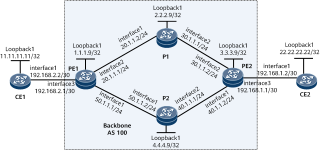
On the network shown in Figure 1, two links exist between PE1 and PE2 in the basic BGP/MPLS IP VPN networking: an LDP LSP (PE1 <-> P1 <-> PE2) and a TE tunnel (PE1 <-> P2 <-> PE2). All VPN traffic is forwarded over the LSP according to the default tunnel policy, which may cause the link of PE1 <-> P1 <-> PE2 to be busy and the link of PE1 <-> P2 <-> PE2 to be idle.
To address this problem, load balancing among tunnels can be configured on the MPLS backbone network to distribute VPN traffic evenly to the two tunnels.

Configuration Notes
When configuring load balancing among tunnels to which remotely leaked VPN routes recurse, ensure that the tunnels existing in the system meet the requirements of the configured tunnel policy.
Configuration Roadmap
The configuration roadmap is as follows:
Configure OSPF on the MPLS backbone network to ensure IP connectivity on the backbone network.
On the MPLS backbone network, enable MPLS and MPLS LDP to set up an LDP LSP.
Configure a VPN instance on each PE and bind the interface that connects CE to PE to the VPN instance on PE.
Establish a TE tunnel between PE1 and PE2 (with P2 as the intermediate node).
Create a tunnel policy on PE1 to distribute traffic to the LDP LSP and MPLS TE tunnel between PE1 and PE2.
Apply the tunnel policy to the VPN instance IPv4 address family on PE1.
Procedure
- Configure a basic BGP/MPLS IP VPN.
For configuration details, see Example for Configuring Basic BGP/MPLS IP VPN. The main configurations are listed as follows:
Configure OSPF on the MPLS backbone network so that the PEs can learn the routes to each other's loopback interface.
Configure MPLS and MPLS LDP both globally and per interface on PE1, P1, and PE2 to set up an LDP LSP along the PEs.
Establish a VPNv4 peer relationship between PEs.
Configure an IPv4-address-family-supporting VPN instance on each PE and bind the interface that connects a PE to a CE to the VPN instance on that PE.
Enable BGP between the PEs and CE, and import the routes to the loopback interface into BGP on the CE.
After completing the configurations, run the display ip routing-table vpn-instance command on PE1. The command output shows that PE1 has learned the route to the loopback interface on the CE.
<PE1> display ip routing-table vpn-instance vpn1
Route Flags: R - relay, D - download to fib, T - to vpn-instance, B - black hole route
------------------------------------------------------------------------------
Routing Table : vpn1
         Destinations : 4        Routes : 4

Destination/Mask    Proto  Pre  Cost        Flags NextHop         Interface

    11.11.11.11/32  EBGP   255  0             D  192.168.2.2     GigabitEthernet0/3/0
    22.22.22.22/32  IBGP   255  0             RD 3.3.3.9         GigabitEthernet0/2/0
<PE1> display ip routing-table vpn-instance vpn1 22.22.22.22 verbose
Route Flags: R - relay, D - download to fib, T - to vpn-instance, B - black hole route
------------------------------------------------------------------------------
Routing Table : vpn1
Summary Count : 1

Destination: 22.22.22.22/32
     Protocol: IBGP            Process ID: 0
   Preference: 255                   Cost: 0
      NextHop: 3.3.3.9          Neighbour: 0.0.0.0
        State: Active Adv Relied      Age: 00h02m28s
          Tag: 0                 Priority: low
        Label: 0x1f               QoSInfo: 0x0
   IndirectID: 0xb7
 RelayNextHop: 20.1.1.2         Interface: GigabitEthernet0/2/0
     TunnelID: 0x0000000001004c4b43 Flags: RD
The command output shows that the route to 22.22.22.22/32 recurses only to one LSP on PE1 because no tunnel policy is applied to the VPN.
- Establish a TE tunnel between PE1 and PE2 (with P2 as the intermediate node).
This example uses an RSVP-TE tunnel. For details, see Example for Configuring an RSVP-TE Tunnel.
- Apply a tunnel policy to the VPN on PE1.
Configure a tunnel policy in select-sequence mode to make tunnels be selected in the order of TE tunnels and LSPs and to set the number of tunnels participating in load balancing to 2.
# Configure PE1.
[~PE1] tunnel-policy te-lsp-l2
[*PE1-tunnel-policy-te-lsp-l2] tunnel select-seq cr-lsp lsp load-balance-number 2
[*PE1-tunnel-policy-te-lsp-l2] quit
# Apply a tunnel policy to the VPN instance IPv4 address family.
[*PE1] ip vpn-instance vpn1
[*PE1-vpn-instance-vpn1] ipv4-family
[*PE1-vpn-instance-vpn1-af-ipv4] tnl-policy te-lsp-l2
[*PE1-vpn-instance-vpn1-af-ipv4] quit
[*PE1-vpn-instance-vpn1] quit
[*PE1] commit
- Verify the configuration.
After completing the configurations, run the display ip routing-table vpn-instance verbose command on PE1. The command output shows that the route to the loopback interface on the CE recurses to two tunnels.
<PE1> display ip routing-table vpn-instance vpn1 22.22.22.22 verbose
Route Flags: R - relay, D - download to fib, T - to vpn-instance, B - black hole route
------------------------------------------------------------------------------
Routing Table : vpn1
Summary Count : 1

Destination: 22.22.22.22/32
     Protocol: IBGP            Process ID: 0
   Preference: 255                   Cost: 0
      NextHop: 3.3.3.9          Neighbour: 0.0.0.0
        State: Active Adv Relied      Age: 00h00m06s
          Tag: 0                 Priority: low
        Label: 0x1f               QoSInfo: 0x0
   IndirectID: 0xbc
 RelayNextHop: 0.0.0.0          Interface: Tunnel10
     TunnelID: 0x000000000300000001 Flags: RD
 RelayNextHop: 20.1.1.2         Interface: GigabitEthernet0/1/8
     TunnelID: 0x0000000001004c4b43 Flags: RD
Configuration Files
PE1 configuration file
#
 sysname PE1
#
ip vpn-instance vpn1
 ipv4-family
 route-distinguisher 100:1
  apply-label per-instance
 tnl-policy te-lsp-l2
 vpn-target 1:1 export-extcommunity
 vpn-target 1:1 import-extcommunity
#
mpls lsr-id 1.1.1.9
#
mpls
 mpls te
 mpls te cspf
 mpls rsvp-te
#
mpls ldp
#
interface GigabitEthernet0/1/0
 undo shutdown
 ip address 50.1.1.1 255.255.255.0
 mpls
 mpls te
 mpls rsvp-te
#
interface GigabitEthernet0/2/0
 undo shutdown
 ip address 20.1.1.1 255.255.255.0
 mpls
 mpls ldp
#
interface GigabitEthernet0/3/0
 undo shutdown
 ip binding vpn-instance vpn1
 ip address 192.168.2.1 255.255.255.252
#
interface LoopBack1
 ip address 1.1.1.9 255.255.255.255
#
interface Tunnel10
 ip address unnumbered interface LoopBack1
 tunnel-protocol mpls te
 destination 3.3.3.9
 mpls te tunnel-id 100
#
bgp 100
 peer 3.3.3.9 as-number 100
 peer 3.3.3.9 connect-interface LoopBack1
 #
 ipv4-family unicast
  undo synchronization
  peer 3.3.3.9 enable
 #
 ipv4-family vpnv4
  policy vpn-target
  peer 3.3.3.9 enable
#
  ipv4-family vpn-instance vpn1
   peer 192.168.2.2 as-number 65420
#
ospf 1
 opaque-capability enable
 area 0.0.0.0
  mpls-te enable
  network 1.1.1.9 0.0.0.0
  network 50.1.1.0 0.0.0.255
  network 20.1.1.0 0.0.0.255
#
tunnel-policy te-lsp-l2
 tunnel select-seq cr-lsp lsp load-balance-number 2
#
return
P1 configuration file
#
 sysname P1
#
mpls lsr-id 2.2.2.9
#
mpls
#
mpls ldp
#
interface GigabitEthernet0/1/0
 undo shutdown
 ip address 20.1.1.2 255.255.255.0
 mpls
 mpls ldp
#
interface GigabitEthernet0/1/8
 undo shutdown
 ip address 30.1.1.1 255.255.255.0
 mpls
 mpls ldp
#
interface LoopBack1
 ip address 2.2.2.9 255.255.255.255
#
ospf 1
 opaque-capability enable
 area 0.0.0.0
  mpls-te enable
  network 2.2.2.9 0.0.0.0
  network 20.1.1.0 0.0.0.255
  network 30.1.1.0 0.0.0.255
#
return
P2 configuration file
#
 sysname P2
#
mpls lsr-id 4.4.4.9
#
mpls
 mpls te
 mpls te cspf
 mpls rsvp-te
#
mpls ldp
#
interface GigabitEthernet0/1/0
 undo shutdown
 ip address 50.1.1.2 255.255.255.0
 mpls
 mpls te
 mpls rsvp-te
#
interface GigabitEthernet0/1/8
 undo shutdown
 ip address 40.1.1.1 255.255.255.0
 mpls
 mpls te
 mpls rsvp-te
#
interface LoopBack1
 ip address 4.4.4.9 255.255.255.255
#
ospf 1
 opaque-capability enable
 area 0.0.0.0
  mpls-te enable
  network 4.4.4.9 0.0.0.0
  network 50.1.1.0 0.0.0.255
  network 40.1.1.0 0.0.0.255
#
return
PE2 configuration file
#
 sysname PE2
#
ip vpn-instance vpn1
 ipv4-family
  route-distinguisher 100:1
  apply-label per-instance
  vpn-target 1:1 export-extcommunity
  vpn-target 1:1 import-extcommunity
#
mpls lsr-id 3.3.3.9
#
mpls
 mpls te
 mpls te cspf
 mpls rsvp-te
#
mpls ldp
#
interface GigabitEthernet0/1/0
 undo shutdown
 ip address 40.1.1.2 255.255.255.0
 mpls
 mpls te
 mpls rsvp-te
#
interface GigabitEthernet0/1/8
 undo shutdown
 ip address 30.1.1.2 255.255.255.0
 mpls
 mpls ldp
#
interface GigabitEthernet0/1/16
 undo shutdown
 ip binding vpn-instance vpn1
 ip address 192.168.1.1 255.255.255.252
#
interface LoopBack1
 ip address 3.3.3.9 255.255.255.255
#
bgp 100
 peer 1.1.1.9 as-number 100
 peer 1.1.1.9 connect-interface LoopBack1
 #
 ipv4-family unicast
  undo synchronization
  peer 1.1.1.9 enable
 #
 ipv4-family vpnv4
  policy vpn-target
  peer 1.1.1.9 enable
#
 ipv4-family vpn-instance vpn1
  peer 192.168.1.2 as-number 65410
#
ospf 1
 opaque-capability enable
 area 0.0.0.0
  mpls-te enable
  network 3.3.3.9 0.0.0.0
  network 30.1.1.0 0.0.0.255
  network 40.1.1.0 0.0.0.255
#
return
CE1 configuration file
#
 sysname CE1
#
interface GigabitEthernet0/1/0
 undo shutdown
 ip address 192.168.2.2 255.255.255.252
#
interface LoopBack1
 ip address 11.11.11.11 255.255.255.255
#
bgp 65420
 peer 192.168.2.1 as-number 100
 #
 ipv4-family unicast
  undo synchronization
  network 11.11.11.11 32
  peer 192.168.2.1 enable
#
return
CE2 configuration file
#
 sysname CE2
#
interface GigabitEthernet0/1/0
 undo shutdown
 ip address 192.168.1.2 255.255.255.252
#
interface LoopBack1
 ip address 22.22.22.22 255.255.255.255
#
bgp 65410
 peer 192.168.1.1 as-number 100
 #
 ipv4-family unicast
  undo synchronization
  network 22.22.22.22 32
  peer 192.168.1.1 enable
#
return