Example for Configuring Hybrid FRR for IPv6 and VPNv6 Routes
If a CE is dual-homed to two PEs, IPv6+VPNv6 hybrid FRR can be configured on PEs to protect the route between either PE and the CE. If the route between either PE and the CE fails, traffic destined for the CE can be switched to the other PE.
Networking Requirements
A CE at an IPv6 VPN site is dual-homed to two PEs, and a VPNv6 peer relationship is set up between the two PEs. To protect the route between the CE and either PE, configure IPv6+VPNv6 hybrid FRR.
If the route between the CE and either PE fails, IPv6+VPNv6 hybrid FRR can quickly switch traffic destined for the CE to the other PE.

IPv6+VPNv6 hybrid FRR applies only to the networking where CEs establish BGP peer relationships with PEs.
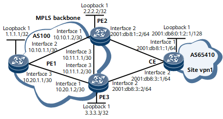
As shown in Figure 1, a CE is dual-homed to PE2 and PE3; an MPLS public network tunnel and a VPNv6 peer relationship are set up between PE2 and PE3. PE2 and PE3 use EBGP to exchange routing information with the CE. PE3 learns from the CE a route to Loopback 1 on the CE and sends the route to its VPNv6 peer. As a result, PE2 has two BGP routes to Loopback 1 on the CE: one is sent from the CE using EBGP, and the other is sent from PE3 using MP-IBGP.
It is required that PE2 be configured to preferentially select the EBGP route sent from the CE for data forwarding and use the VPNv6 route sent from PE3 as a backup route. If the route between PE2 and the CE fails, the traffic can be switched to PE3 that serves as the backup next hop.
Configuration Notes
In a VPN hybrid FRR scenario, after the primary path recovers, traffic is switched back to the primary path. Because the order in which nodes undergo IGP convergence differs, packet loss may occur during the switchback. To resolve this problem, run the route-select delay delay-value command to configure a route selection delay so that traffic is switched back only after forwarding entries on the devices along the primary path are updated. The delay specified using delay-value depends on various factors, such as the number of routes on the devices. Set a proper delay as needed.
Configuration Roadmap
The configuration roadmap is as follows:
Configure OSPF on the MPLS backbone network for IP connectivity between PE1, PE2, and PE3.
Configure MPLS and MPLS LDP both globally and per interface on each node of the MPLS backbone network and establish LDP LSPs.
Establish an MP-IBGP peer relationship between PE1, PE2, and PE3.
Configure an IPv6-address-family-supporting VPN instance on each PE, and bind the interface that connects a PE to a CE to the VPN instance on that PE.
Establish an EBGP peer relationship between PE2 and the CE, and between PE3 and the CE, and import the routes to the loopback interface into BGP on the CE.
Configure auto FRR for the BGP-VPN instance IPv6 address family on PE2 so that the VPNv6 route sent from PE3 can serve as a backup route.
Procedure
- Configure IPv4 addresses for interfaces on the MPLS backbone network and IPv6 addresses for interfaces at the VPN site. For configuration details, see Configuration Files in this section.
- Configure OSPF on the MPLS backbone network for IP connectivity between PEs. For configuration details, see Configuration Files in this section.
- Configure MPLS and MPLS LDP both globally and per interface on each node of the MPLS backbone network and establish LDP LSPs.
# Configure PE1.
<PE1> system-view
[~PE1] mpls lsr-id 1.1.1.1
[*PE1] mpls
[*PE1-mpls] quit
[*PE1] mpls ldp
[*PE1-mpls-ldp] quit
[*PE1] interface gigabitEthernet0/1/8
[*PE1-GigabitEthernet0/1/8] mpls
[*PE1-GigabitEthernet0/1/8] mpls ldp
[*PE1-GigabitEthernet0/1/8] quit
[*PE1] interface gigabitEthernet0/1/16
[*PE1-GigabitEthernet0/1/16] mpls
[*PE1-GigabitEthernet0/1/16] mpls ldp
[*PE1-GigabitEthernet0/1/16] quit
[*PE1] commit
# Configure PE2.
<PE2> system-view
[~PE2] mpls lsr-id 2.2.2.2
[*PE2] mpls
[*PE2-mpls] quit
[*PE2] mpls ldp
[*PE2-mpls-ldp] quit
[*PE2] interface gigabitEthernet0/1/0
[*PE2-GigabitEthernet0/1/0] mpls
[*PE2-GigabitEthernet0/1/0] mpls ldp
[*PE2-GigabitEthernet0/1/0] quit
[*PE2] interface gigabitEthernet0/1/16
[*PE2-GigabitEthernet0/1/16] mpls
[*PE2-GigabitEthernet0/1/16] mpls ldp
[*PE2-GigabitEthernet0/1/16] quit
[*PE2] commit
# Configure PE3.
<PE3> system-view
[~PE3] mpls lsr-id 3.3.3.3
[*PE3] mpls
[*PE3-mpls] quit
[*PE3] mpls ldp
[*PE3-mpls-ldp] quit
[*PE3] interface gigabitEthernet0/1/0
[*PE3-GigabitEthernet0/1/0] mpls
[*PE3-GigabitEthernet0/1/0] mpls ldp
[*PE3-GigabitEthernet0/1/0] quit
[*PE3] interface gigabitEthernet0/1/16
[*PE3-GigabitEthernet0/1/16] mpls
[*PE3-GigabitEthernet0/1/16] mpls ldp
[*PE3-GigabitEthernet0/1/16] quit
[*PE3] commit
Run the display mpls lsp command on PEs. The command output shows that LSPs are set up between PE1 and PE2, and between PE1 and PE3. The following example uses the command output on PE1.
[*PE1] display mpls lsp
2021-04-09 01:14:17.813
Flag after Out IF: (I) - RLFA Iterated LSP, (I*) - Normal and RLFA Iterated LSP
Flag after LDP FRR: (L) - Logic FRR LSP
----------------------------------------------------------------------
                 LSP Information: LDP LSP
----------------------------------------------------------------------
FEC                In/Out Label  In/Out IF                      Vrf Name
2.2.2.2/32         NULL/3        -/GE0/1/8
2.2.2.2/32         1024/3        -/GE0/1/8
3.3.3.3/32         NULL/3        -/GE0/1/16
3.3.3.3/32         1025/3        -/GE0/1/16
- Establish an MP-IBGP peer relationship between PEs.
# Configure PE1.
[~PE1] bgp 100
[*PE1-bgp] peer 2.2.2.2 as-number 100
[*PE1-bgp] peer 2.2.2.2 connect-interface loopback 1
[*PE1-bgp] peer 3.3.3.3 as-number 100
[*PE1-bgp] peer 3.3.3.3 connect-interface loopback 1
[*PE1-bgp] ipv6-family vpnv6
[*PE1-bgp-af-vpnv6] peer 2.2.2.2 enable
[*PE1-bgp-af-vpnv6] peer 3.3.3.3 enable
[*PE1-bgp-af-vpnv6] quit
[*PE1-bgp] quit
[*PE1] commit
# Configure PE2.
[~PE2] bgp 100
[*PE2-bgp] peer 1.1.1.1 as-number 100
[*PE2-bgp] peer 1.1.1.1 connect-interface loopback 1
[*PE2-bgp] peer 3.3.3.3 as-number 100
[*PE2-bgp] peer 3.3.3.3 connect-interface loopback 1
[*PE2-bgp] ipv6-family vpnv6
[*PE2-bgp-af-vpnv6] peer 1.1.1.1 enable
[*PE2-bgp-af-vpnv6] peer 3.3.3.3 enable
[*PE2-bgp-af-vpnv6] quit
[*PE2-bgp] quit
[*PE2] commit
# Configure PE3.
[~PE3] bgp 100
[*PE3-bgp] peer 1.1.1.1 as-number 100
[*PE3-bgp] peer 1.1.1.1 connect-interface loopback 1
[*PE3-bgp] peer 2.2.2.2 as-number 100
[*PE3-bgp] peer 2.2.2.2 connect-interface loopback 1
[*PE3-bgp] ipv6-family vpnv6
[*PE3-bgp-af-vpnv6] peer 1.1.1.1 enable
[*PE3-bgp-af-vpnv6] peer 2.2.2.2 enable
[*PE3-bgp-af-vpnv6] quit
[*PE3-bgp] quit
[*PE3] commit
After completing the configurations, run the display bgp vpnv6 all peer command on the PEs. The command output shows that the status of the MP-IBGP peer relationship between the PEs is Established.
The following example uses the command output on PE1.
[~PE1] display bgp vpnv6 all peer BGP local router ID : 1.1.1.1 Local AS number : 100 Total number of peers : 2 Peers in established state : 2 Peer V AS MsgRcvd MsgSent OutQ Up/Down State PrefRcv 2.2.2.2 4 100 20 17 0 00:13:26 Established 5 3.3.3.3 4 100 24 19 0 00:17:18 Established 5 - Configure an IPv6-address-family-supporting VPN instance on each PE, and bind the interface that connects a PE to a CE to the VPN instance on that PE.
# Configure PE1.
[~PE1] ip vpn-instance vpn1
[*PE1-vpn-instance-vpn1] ipv6-family
[*PE1-vpn-instance-vpn1-af-ipv6] route-distinguisher 100:1
[*PE1-vpn-instance-vpn1-af-ipv6] vpn-target 111:1
[*PE1-vpn-instance-vpn1-af-ipv6] quit
[*PE1-vpn-instance-vpn1] quit
[*PE1] commit
# Configure PE2.
[~PE2] ip vpn-instance vpn1
[*PE2-vpn-instance-vpn1] ipv6-family
[*PE2-vpn-instance-vpn1-af-ipv6] route-distinguisher 100:2
[*PE2-vpn-instance-vpn1-af-ipv6] vpn-target 111:1
[*PE2-vpn-instance-vpn1-af-ipv6] quit
[*PE2-vpn-instance-vpn1] quit
[*PE2] interface gigabitethernet0/1/8
[*PE2-GigabitEthernet0/1/8] ip binding vpn-instance vpn1
[*PE2-GigabitEthernet0/1/8] ipv6 enable
[*PE2-GigabitEthernet0/1/8] ipv6 address 2001:db8:1::2 64
[*PE2-GigabitEthernet0/1/8] quit
[*PE2] commit
# Configure PE3.
[~PE3] ip vpn-instance vpn1
[*PE3-vpn-instance-vpn1] ipv6-family
[*PE3-vpn-instance-vpn1-af-ipv6] route-distinguisher 100:3
[*PE3-vpn-instance-vpn1-af-ipv6] vpn-target 111:1
[*PE3-vpn-instance-vpn1-af-ipv6] quit
[*PE3-vpn-instance-vpn1] quit
[*PE3] interface gigabitethernet0/1/8
[*PE3-GigabitEthernet0/1/8] ip binding vpn-instance vpn1
[*PE3-GigabitEthernet0/1/8] ipv6 enable
[*PE3-GigabitEthernet0/1/8] ipv6 address 2001:db8:3::2 64
[*PE3-GigabitEthernet0/1/8] quit
[*PE3] commit
- Establish an EBGP peer relationship between PE2 and the CE, and between PE3 and the CE, and import the routes to the loopback interface into BGP on the CE.
# Configure PE2.
[~PE2] bgp 100
[*PE2-bgp] ipv6-family vpn-instance vpn1
[*PE2-bgp6-vpn1] peer 2001:db8:1::1 as-number 65410
[*PE2-bgp6-vpn1] quit
[*PE2-bgp] quit
[*PE2] commit
# Configure PE3.
[~PE3] bgp 100
[*PE3-bgp] ipv6-family vpn-instance vpn1
[*PE3-bgp6-vpn1] peer 2001:db8:3::1 as-number 65410
[*PE3-bgp6-vpn1] quit
[*PE3-bgp] quit
[*PE3] commit
# Configure the CE.
[~CE] bgp 65410
[*CE-bgp] router-id 10.10.10.10
[*CE-bgp] peer 2001:db8:1::2 as-number 100
[*CE-bgp] peer 2001:db8:3::2 as-number 100
[*CE-bgp] ipv6-family unicast
[*CE-bgp-af-ipv6] peer 2001:db8:1::2 enable
[*CE-bgp-af-ipv6] peer 2001:db8:3::2 enable
[*CE-bgp-af-ipv6] network 2001:db8:0:1:2::1 128
[*CE-bgp-af-ipv6] quit
[*CE-bgp] quit
[*CE] commit
After completing the configurations, run the display ipv6 routing-table vpn-instance command on PE2. The command output shows the route to the loopback interface on the CE.<PE2> display ipv6 routing-table vpn-instance vpn1 2001:db8:0:1:2::1 128 Routing Table : vpn1 Summary Count : 1 Destination : 2001:db8:0:1:2::1 PrefixLength : 128 NextHop : 2001:db8:1::1 Preference : 255 Cost : 0 Protocol : EBGP RelayNextHop : 2001:db8:1::1 TunnelID : 0x0 Interface : GigabitEthernet0/1/8 Flags : RD - Configure VPNv6 auto FRR on PE2, and adjust the precedence of EBGP routes for PE2 to preferentially select an EBGP route.
# Configure PE2.
[~PE2] bgp 100
[~PE2-bgp] ipv6-family vpn-instance vpn1
[*PE2-bgp6-vpn1] preference 100 255 255
[*PE2-bgp6-vpn1] auto-frr
[*PE2-bgp6-vpn1] route-select delay 300
[*PE2-bgp6-vpn1] quit
[*PE2-bgp] quit
[*PE2] commit
- Verify the configuration.
After completing the configurations, run the display ipv6 routing-table vpn-instance verbose command on PE2. The command output shows information about the primary and backup routes to the loopback interface on the CE in the routing table of the VPN instance IPv6 address family. Because the EBGP route takes precedence over the IBGP route, PE2 selects the EBGP route sent from the CE to forward data and uses the IBGP route sent from PE3 as the backup route. The boldfaced text shows information about the backup next hop, backup label, and backup tunnel ID, indicating that an IPv6+VPNv6 hybrid FRR entry has been generated.
<PE2> display ipv6 routing-table vpn-instance vpn1 2001:db8:0:1:2::1 verbose
Routing Table : vpn1
Summary Count : 1

 Destination  : 2001:db8:0:1:2::1               PrefixLength : 128
 NextHop      : 2001:db8:1::1                   Preference   : 100
 Neighbour    : ::                              ProcessID    : 0
 Label        : NULL                            Protocol     : BGP
 State        : Active Adv Relied               Cost         : 0
 Entry ID     : 14                              EntryFlags   : 0x00000000
 Reference Cnt: 0                               Tag          : 0
 IndirectID   : 0x8a9                           Age          : 3sec
 RelayNextHop : 2001:db8:1::1                   TunnelID     : 0x0
 Interface    : GigabitEthernet0/1/8            Flags        : RD
 BkNextHop    : ::                              BkInterface  : LDP LSP
 BkLabel      : 17                              BkTunnelID   : 0x0
 BkPETunnelID : 0x0000000001004c4b44            BkIndirectID : 0xae
Run the shutdown and display ipv6 routing-table vpn-instance verbose commands on GE 0/1/8 of PE2. The next hop of the route from PE2 to the loopback interface of the CE is switched to PE3.
<PE2> display ipv6 routing-table vpn-instance vpn1 2001:db8:0:1:2::1 verbose
Routing Table : vpn1
Summary Count : 1

 Destination  : 2001:db8::0:1:2::1              PrefixLength : 128
 NextHop      : ::FFFF:3.3.3.3                  Preference   : 255
 Neighbour    : ::                              ProcessID    : 0
 Label        : 17                              Protocol     : BGP
 State        : Active Adv Relied               Cost         : 0
 Entry ID     : 0                               EntryFlags   : 0x00000000
 Reference Cnt: 0                               Tag          : 0
 IndirectID   : 0xa5                            Age          : 9sec
 RelayNextHop : ::                              TunnelID     : 0x0000000001004c4b42
 Interface    : GigabitEthernet0/1/8            Flags        : RD
IPv6+VPNv6 hybrid FRR has taken effect on PE2.
Configuration Files
PE1 configuration file
#
 sysname PE1
#
ip vpn-instance vpn1
 ipv6-family
  route-distinguisher 100:1
  apply-label per-instance
  vpn-target 111:1 export-extcommunity
  vpn-target 111:1 import-extcommunity
#
mpls lsr-id 1.1.1.1
#
mpls
#
mpls ldp
#
interface GigabitEthernet0/1/8
 undo shutdown
 ip address 10.10.1.1 255.255.255.252
 mpls
 mpls ldp
#
interface GigabitEthernet0/1/16
 undo shutdown
 ip address 10.20.1.1 255.255.255.252
 mpls
 mpls ldp
#
interface LoopBack1
 ip address 1.1.1.1 255.255.255.255
#
bgp 100
 peer 2.2.2.2 as-number 100
 peer 2.2.2.2 connect-interface LoopBack1
 peer 3.3.3.3 as-number 100
 peer 3.3.3.3 connect-interface LoopBack1
 #
 ipv4-family unicast
  undo synchronization
  peer 2.2.2.2 enable
  peer 3.3.3.3 enable
#
 ipv6-family vpnv6
  policy vpn-target
  peer 2.2.2.2 enable
  peer 3.3.3.3 enable
#
 ipv6-family vpn-instance vpn1
 import-route direct
#
ospf 1
 area 0.0.0.0
  network 10.10.1.0 0.0.0.3
  network 10.20.1.0 0.0.0.3
  network 1.1.1.1 0.0.0.0
#
return
PE2 configuration file
#
 sysname PE2
#
ip vpn-instance vpn1
 ipv6-family
  route-distinguisher 100:2
  apply-label per-instance
  vpn-target 111:1 export-extcommunity
  vpn-target 111:1 import-extcommunity
#
mpls lsr-id 2.2.2.2
#
mpls
#
mpls ldp
#
interface GigabitEthernet0/1/0
 undo shutdown
 ip address 10.10.1.2 255.255.255.252
 mpls
 mpls ldp
#
interface GigabitEthernet0/1/8
 undo shutdown
 ipv6 enable
 ip binding vpn-instance vpn1
 ipv6 address 2001:db8:1::2/64
#
interface GigabitEthernet0/1/16
 undo shutdown
 ip address 10.11.1.1 255.255.255.252
 mpls
 mpls ldp
#
interface LoopBack1
 ip address 2.2.2.2 255.255.255.255
#
bgp 100
 peer 1.1.1.1 as-number 100
 peer 1.1.1.1 connect-interface LoopBack1
 peer 3.3.3.3 as-number 100
 peer 3.3.3.3 connect-interface LoopBack1
 #
 ipv4-family unicast
  undo synchronization
  peer 1.1.1.1 enable
  peer 3.3.3.3 enable
#
 ipv6-family vpnv6
  policy vpn-target
  peer 1.1.1.1 enable
  peer 3.3.3.3 enable
#
 ipv6-family vpn-instance vpn1
  preference 100 255 255
  auto-frr
  route-select delay 300
  peer 2001:db8:1::1 as-number 65410
#
ospf 1
 area 0.0.0.0
  network 10.10.1.0 0.0.0.3
  network 10.11.1.0 0.0.0.3
  network 2.2.2.2 0.0.0.0
#
return
PE3 configuration file
#
 sysname PE3
#
ip vpn-instance vpn1
 ipv6-family
  route-distinguisher 100:3
  apply-label per-instance
  vpn-target 111:1 export-extcommunity
  vpn-target 111:1 import-extcommunity
#
mpls lsr-id 3.3.3.3
#
mpls
#
mpls ldp
#
interface GigabitEthernet0/1/0
 undo shutdown
 ip address 10.20.1.2 255.255.255.252
 mpls
 mpls ldp
#
interface GigabitEthernet0/1/8
 undo shutdown
 ipv6 enable
 ip binding vpn-instance vpn1
 ipv6 2001:db8:3::2/64
#
interface GigabitEthernet0/1/16
 undo shutdown
 ip address 10.11.1.2 255.255.255.252
 mpls
 mpls ldp
#
interface LoopBack1
 ip address 3.3.3.3 255.255.255.255
#
bgp 100
 peer 1.1.1.1 as-number 100
 peer 1.1.1.1 connect-interface LoopBack1
 peer 2.2.2.2 as-number 100
 peer 2.2.2.2 connect-interface LoopBack1
 #
 ipv4-family unicast
  undo synchronization
  peer 1.1.1.1 enable
  peer 2.2.2.2 enable
#
 ipv6-family vpnv6
  policy vpn-target
  peer 1.1.1.1 enable
  peer 2.2.2.2 enable
#
 ipv6-family vpn-instance vpn1
  preference 100 255 255
  auto-frr
  peer 2001:db8:3::1 as-number 65410
#
ospf 1
 area 0.0.0.0
  network 10.20.1.0 0.0.0.3
  network 10.11.1.0 0.0.0.3
  network 3.3.3.3 0.0.0.0
#
Return
CE configuration file
#
 sysname CE
#
interface GigabitEthernet0/1/0
 undo shutdown
 ipv6 enable
 ipv6 address 2001:db8:1::1/64
#
interface GigabitEthernet0/1/8
 undo shutdown
 ipv6 enable
 ipv6 address 2001:db8:3::1/64
#
interface LoopBack1
 ipv6 enable
 ipv6 address 2001:db8:0:1:2::1/128
#
bgp 65410
 router-id 10.10.10.10
 peer 2001:db8:1::2 as-number 100
 peer 2001:db8:3::2 as-number 100
 #
 ipv4-family unicast
  undo synchronization
 #
 ipv6-family unicast
  undo synchronization
  network 2001:db8:0:1:2::1 128
  peer 2001:db8:1::2 enable
  peer 2001:db8:3::2 enable
#
return